Quantcast
Channel: Prosthodontics | Dentistry Today
Viewing all 50 articles
Browse latest View live

Upgrading From a Removable to a Fixed Prosthesis

$
0
0

Over the years, as general dentists, we will see many patients in our offices who have been treated with different types of implant restorations.1 We may or may not have had the opportunity to plan the prosthesis that the patient is wearing, but we have to learn how to manage a variety of cases. In situations where the patient feels uncomfortable or is unable to function properly, we need to be able to determine if we can provide an appropriate solution.2

CASE REPORT
Diagnosis and Treatment Planning

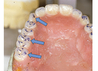
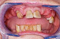
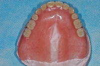
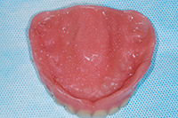
Our patient was previously treated in 2001 with a maxillary implant-retained tissue-supported partial overdenture, extending from the maxillary right first molar to the maxillary left first premolar3 (Figure 1). The overdenture was retained by 4 o-ring abutments on implants placed in the anterior maxilla (Figure 2). This particular design created 2 posterior cantilevers bilaterally in the acrylic partial overdenture.4,5 The existing acrylic material lacked adequate thickness and strength due to the limited interarch space available, providing another factor that made this partial overdenture prone to fracture.6 Lastly, all the implants were placed in positions that did not correctly fit the position of natural teeth, emerging instead between the teeth interproximally (Figure 3).

Figure 1. Existing o-ring partial overdenture. Figure 2. O-ring abutments in anterior maxilla.
Figure 3. Implants, previously placed, emerged interproximally in relation to the natural tooth positions. Figure 4. Broken partial overdenture.

Originally, the patient had presented to our office with one of several broken maxillary o-ring partial overdentures, requesting a repair (Figure 4). We were able to do the repair, and we also gave the patient a good amount of information about alternative treatment options. We explained the reasons why her present situation would continue to give her the problems that she had been struggling with for years. When we saw her again the following year, she had made the decision to proceed with the additional work needed to improve her dental condition.
Initial records consisted of a standard intra- and extraoral photographic series, and a panoramic radiograph (Figure 5) supplemented by several periapical radiographs. Study models were mounted in centric relation using a stick-bite registration and face-bow record. This information allowed us to properly assess the patient’s clinical situation, and to design a treatment plan that would result in a comfortable, functional, and durable prosthesis.
The following existing conditions were noted at the time of the initial examination:

  • Semi-edentulous maxillary arch against mandibular natural teeth (only Nos. 2, 13, 14, and 15 remain).
  • Interarch space of 8 to 9 mm when patient is in occlusion.
  • Supra-erupted maxillary molars restored with PFMs.
  • A one-tooth distal cantilever on the left, and a 2-tooth distal cantilever on right.
  • Slight labial placement and angle of 2 implants on right.
  • Sinus problems, with a history of sinus surgery.
  • Needs replacement of several crown and bridge, and composite restorations.

There were no clinical signs of temporomandibular dysfunction and her medical history was noncontributory.
A fixed partial denture was proposed that would include sinus grafting and the addition of 2 or 3 more implants, after an ear, nose, and throat evaluation and treatment of the sinuses. However, the patient refused to proceed with this plan, so a compromised plan was agreed upon. She agreed to have one additional implant placed (as far distally as the anterior wall of the sinus would permit without encroaching upon it) in order to reduce the length of the distal cantilever on the right, yet still be able to give her a fixed prosthesis.7 Since a fixed prosthesis requires less interarch distance than a removable one, this measurement was no longer a concern; however, the emergence of the 4 anterior implants still presented a problem. It was determined that the highest extent of her smile-line was low enough that she did not have any gingival exposure, and the patient was amenable to having the incorrect emergence masked with pink porcelain.8

Figure 5. Panoramic radiograph. Figure 6. Additional implant, close to anterior wall of the sinus.
Figure 7. Radiograph of pick-up impression copings. Figure 8. Face-bow mounting.
Figure 9. Abutment seating, verified with bitewing radiographs.

One of the concerns in treating the case was the identification of the implants and finding the necessary components to make the change in design. The implants were identified (Zimmer Spline 3.25 cylinders), and we were glad to learn that all the parts that would be needed to restore the case were still available.

A Synopsis of the Clinical Treatment and Laboratory Work
The patient received one additional implant (Zimmer Screw-vent 3.4 x 11.5) close to the right anterior sinus wall (Figure 6), and after a 5-month waiting period for osseointegration, the case was ready to begin the prosthetic phase of treatment.
The impression copings of the Spline system were much wider than the 3.25 prosthetic platform of the implants, requiring a local anesthetic. They were pick-up copings (Figure 8) and required an open-tray impression to compensate for the divergent angles.9,10 The impression was taken with a vinyl polysiloxane (VPS) material (Genie VPS Impression Material [Sultan Healthcare]) using a regular body/light body technique.11

Figure 10. Radiographs of the completed case.
Figure 11. The new completed maxillary fixed partial denture.

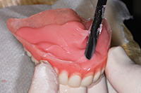
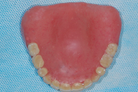
In the dental laboratory, a soft-tissue model was created and mounted on a semi-adjustable articulator (Whip-Mix 8300 [Whip-Mix]) utilizing a face-bow transfer and stick-bite records (Figure 9). Gold waxing sleeves were used to create and cast custom abutments. The fixed partial denture was fabricated of PFM (the laboratory used InLine porcelain and W-1 noble metal, both by Ivoclar Vivadent). A layered zirconia alternative had been considered, but conventional PFM technology was chosen because of the distal cantilevers.6
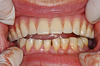
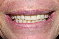
The abutments were returned to the dental office and tried-in the patient, verifying the fit with bite-wing radiographs (Figure 10). They were then torqued to 30 Ncm. Next, the fixed partial denture was tried-in and adjusted for proper canine guidance, and anterior function in lateral and protrusive movements. Then, the prosthesis was cemented with a temporary implant cement (Premier Implant Cement [Premier Dental Products]) (Figure 11). An intraoral photograph of the finished case can be seen in Figure 12.
The patient has been functioning comfortably for more than one year with her new fixed prosthesis and remains very happy with the results.

IN SUMMARY
This article presented a case report showcasing a maxillary removable overdenture patient who had experienced a less-than-ideal outcome. Using sound treatment planning and accepted technical principles, the original prosthesis was converted into a fixed partial denture, resulting in a positive functional solution for the patient.F

Acknowledgement
The author would like to thank Jay Black of Winter Springs Dental Lab, Winter Springs, Fla for the laboratory work.


References

  1. Christensen GJ. Implants and general practitioners. J Am Dent Assoc. 2000;131:359-361.
  2. Caplanis N, Kan JY, Lozada JL. Implant dentistry education for the practicing dentist. J Calif Dent Assoc. 2001;29:757-764.
  3. Att W, Bernhart J, Strub JR. Fixed rehabilitation of the edentulous maxilla: possibilities and clinical outcome. J Oral Maxillofac Surg. 2009;67(suppl 11):60-73.
  4. Crothers AJ, Wassell RW, Jepson N, et al. The use of cantilever bridges. Dent Update. 1995;22:190-198.
  5. Hill EE. Decision-making for treatment planning a cantilevered fixed partial denture. Compend Contin Educ Dent. 2009;30:580-585.
  6. Eraslan O, Sevimay M, Usumez A, et al. Effects of cantilever design and material on stress distribution in fixed partial dentures—a finite element analysis. J Oral Rehabil. 2005;32:273-278.
  7. Himmel R, Pilo R, Assif D, et al. The cantilever fixed partial denture—a literature review. J Prosthet Dent. 1992;67:484-487.
  8. Kourkouta S. Implant therapy in the esthetic zone: smile line assessment. Int J Periodontics Restorative Dent. 2011;31:195-201.
  9. Jo SH, Kim KI, Seo JM, et al. Effect of impression coping and implant angulation on the accuracy of implant impressions: an in vitro study. J Adv Prosthodont. 2010;2:128-133.
  10. Conrad HJ, Pesun IJ, DeLong R, et al. Accuracy of two impression techniques with angulated implants. J Prosthet Dent. 2007;97:349-356.
  11. Donovan TE, Chee WW. A review of contemporary impression materials and techniques. Dent Clin North Am. 2004;48:vi-vii, 445-470.

Dr. Boudet is a graduate of the Medical College of Virginia in Richmond, Va. After graduating with a DDS degree in 1980, he became a commissioned officer for the United States Public Health Service. He established his dental practice in West Palm Beach, Fla, in 1983. Dr. Boudet is a Diplomate of the International Congress of Oral Implantologists and is on the board of directors of the Atlantic Coast Dental Research Clinic. He can be reached via e-mail at themouthman@yahoo.com or visit the Web site boudetdds.com.

Disclosure: Dr. Boudet reports no disclosures.


Prerequisites for Trouble-Free Fully Functional Dentures

$
0
0

MOLECULAR ADHESION
The first prerequisite is adhesion, the focus of the article “Dread-Free Compound Impressions in Half the Time” published in Dentistry Today in September 2006 view the article at dentistrytoday.com). That article discussed how mucostatic impressions, if taken properly, would result in models that were almost clones of the patient’s ridges. This would give the molecular adhesion needed and desired in the resulting dentures, like the adhesion between 2 glass slabs.

SEMI-PROCESSED BASES
The second prerequisite is to prove at the bite-rim stage (read the article “Semi-Processed Bite Rims for Dentures” published in Dentistry Today, August 2007, or visit dentistrytoday.com) that the models are accurate enough to produce bases with molecular adhesion. Semi-processed acrylic bases, as seen in Figures 1 and 2, are used to make the bite rims. If these bite rims with the semiprocessed bases prove to have the molecular adhesion that is desired in the mouth, then these bases and models are mounted on a semi-adjustable articulator, appropriate teeth are selected and set, and the new bases are fully processed.

MOUNTING THE BASES
The next 3 prerequisites describe how the author was taught to accurately mount bite rims and models using an interarch tracer (Simplex Intra Oral Gothic Arch Tracing Device [DENTSPLY Prosthetics]).

Figure 1. Semiprocessed bite rim. Figure 2. Bare ridges for added
vertical and retention.
Figure 3. Conventional mounting of models. Figure 4. Interarch tracer for fully functional dentures.

First, the models and rims are mounted with a centric bite (Figure 3) using a face-bow registration, etc. Then, the interarch tracer is applied (Figure 4).
The interarch tracer is used to accurately remount the lower model. This remounting of the lower model is an inexpensive 30-minute procedure that not only produces a corrected plane of occlusion, but it also provides the operator an assured (not assumed) centric relation mounting. Last, but not least, this interarch tracing provides the patient’s lateral and protrusive settings for the eminentia on the articulator. Without this patient’s eminentia settings, one cannot produce fully functional dentures. No 2 people have the same eminentia settings. (Read the article “Fabricating Fully Functional Dentures” published in Dentistry Today, November 2009, or visit dentistrytoday.com.).

ADDING TEETH TO THE BASES
Now, the wax rim measurements taken in the mouth, older photos of the patient, etc, are used to select the teeth. The author always uses 33° all-porcelain teeth (Trubyte Bioblend [anteriors] and Trubyte Bioform VF 33° [posteriors] [DENTSPLY Prosthetics]), and to avoid grinding away the retentive areas, the ridges are left bare (Figures 1 and 2). This not only allows more vertical room to set the teeth, but it also secures the wax additions to the acrylic bases. Note: The palate is also left void to facilitate the ruggae pattern insertion in the final wax-up (Figure 5). These ruggae not only aid in phonetics, they also give the tongue more traction in closures.

FUNCTIONAL OCCLUSION
To begin setting the teeth, we must first lock the articulator in centric. The author’s sixth prerequisite is the use of the 20° posterior template (TruByte) for setting the upper teeth. This 20° plane alters the flat occlusal plane of the wax rim set by the Fox plane to be curved, the curve of Wilson mesiodistally, and the curve of Spee anteroposteriorly. Without this plane correction, a fully functional setup is not possible.

SETTING TEETH MADE EASY
Setting the upper anterior teeth, one tooth at a time, to the labial parameters of the wax rims, and the 20° plane and the crest of the ridges, one can see the resulting setup in Figure 6. We now set the first premolar on the 20° plane, making sure the lingual cusp tip hits dead-center on the lower midline upon closure (Figure 7). Finish setting the upper left in the same manner (Figure 8). One can now visualize how the curve of Spee sets the plane of occlusion in relation to the curve of the lower ridge (Figure 9). This curved occlusal relationship of the upper teeth to the curved lower ridges gives the dentures added stability while the dentures are functioning, and prevents the lower denture from rotating forward (distomesial), which can cause the elusive sore spots.

COPYING NATURE
Having set the upper teeth in extra hard pink wax (Miltex), the occlusal anatomy of these 33° porcelain teeth will set themselves. Each lower tooth is placed in heated wax and locked into maximum intercuspation (MI) with its opposing upper tooth, while closing into the set vertical (Figure 10). This is the way nature sets the natural teeth during eruption when the infant swallows with the tongue, setting the vertical. Finish setting the lower posteriors in the same manner.

Figure 5. Upper waxed-up denture, ready for processing. Figure 6. Twenty-degree plane to set uppers.
Figure 7. Lingual cusps hitting dead center. Figure 8. Twenty-degree plane for curve of Wilson and curve of Spee.
Figure 9. Curve of Wilson matches the lower ridge. Figure 10. Occlusal anatomy sets lower teeth.
Figure 11. Setting lower anterior teeth in protrusive. Figure 12. Lateral disclusion for shredding (chewing) efficiency.
Figure 13. Left cuspid disclusion in mouth. Figure 14. Remount of the processed upper denture.

Unlock the articulator so that the lower anteriors can be set by protruding the mandible one-half tooth to where the opposing cusp tips are apex to apex (Figure 11). While the posteriors are in this protruded position, the lower incisors are set edge-to-edge with corresponding upper incisors. This protrusive cuspid disclusion is created by having the distal marginal ridge of the upper cuspid ride up the mesial marginal ridge of the lower first premolar. In this protrusive move, the lower cuspid slides through the space left by the upper lateral not touching the 20° plane. This prevents the upper denture from being dislodged by the lower cuspid in protrusive. This added height of the lower cuspid provides for the lateral disclusion (Figures 12 and 13). By varying the height of the lower cuspid (Figure 12), we can control how close the opposing marginal ridges approximate each other without actually touching. In centric closure, the marginal ridges are like cookie cutters when closing into MI, and the shredding of the food is provided by the action of these marginal ridges in lateral excursions. Without the patient’s eminentia settings, any lateral and protrusive moves would not only result in the denture’s coming loose, but with porcelain teeth, there would be a clicking noise.

THE PROOF IS IN THE PUDDING
Now set the teeth on the right side in the same manner as was done on the left, and then the denture setups are ready for a wax try-in. The author always chills the setups in ice cold water before taking them into the mouth. This hardens the wax and prevents the individual teeth from moving with any prematurities. I want the dentures to lose adhesion if there are any prematurities in the occlusion. (Note: Never use adhesives during the wax try-in!)

Table. The Author’s Vision of a Perfect Denture
A denture that seats passively on its ridges when the teeth are separated (molecular adhesion)
A denture that is in centric relation prior to closure
A denture that will remain in centric relation on closure into maximum intercuspation (centric relation = centric occlusion)
A denture that will not dislodge while functioning
A denture that will enhance aesthetics and phonetics
A denture that is still seated passively on its ridges on opening after closure.


Having set the upper anteriors with the 20° plane and the lower anteriors set with the protrusive moves determined by the patient’s eminentia settings, the patient’s phonetics should be perfect. (Note: I mentioned this improvement in phonetics to a prospective denture patient, and she asked if she would be able to sing. I replied, “I’m sure you will be able to sing.” She was so pleased. She said, “That’s wonderful; I’ve never been able to sing before.”)

ALL CAN STILL BE LOST
Assuming the wax try-in went well, we are ready to replace the semi-processed acrylic bases with fully processed plastic bases. The author’s final prerequisite involves the use of remounting grooves. If you have never been to a commercial dental laboratory to see how dentures are processed, you should consider making it a priority to do so.
With remounting grooves on the bases of your models (Figure 2), you can be the quality control in the processing procedures. After the try-in, send the dentures on their articulator for finalizing the wax-up with specific instructions to have the final wax-up remounted for your approval. Check the occlusion of the remounted wax-up to see if you still have MI on every closure, etc. If all is well, remove the upper model from the articulator (Figure 5) and send it to the laboratory for processing. Again, issue specific instructions not to remove the denture from the model after processing—this is because it should be remounted on the articulator opposing the lower denture still in wax. After remounting the processed upper to the lower still in wax, make all corrections to the occlusion by moving the lower teeth still in wax (Figures 14 to 16). (Note: In these Figures, a case where there were severe changes to the occlusion in the processing of the upper denture is demonstrated. Usually, assuming one uses an excellent dental laboratory, these changes in the occlusion are less severe. You will find, however, that any changes will still require correcting the occlusion to MI by moving the opposing teeth while they are still in wax.)

Figure 15. Corrections made to lower still in wax. Figure 16. Lower denture is now ready for processing.
Figure 17. Final occlusal
adjustments.
Figure 18. Checking protrusive movements.
Figure 19. Final correction. Figure 20. Pressure indicator paste corrections.
Figure 21. Maximum intercuspation is observed on every closure.

There should be no grinding of the occlusion. Once MI is observed again on every closure, the lower model is sent into the laboratory for processing; with the same instructions not to remove the processed denture from its model, for it is to be remounted to the processed upper denture that is still on the articulator. Then, final adjustments to the occlusion are made (Figures 17 and 18). Once the occlusion is locked into MI on every closure, and the dentures can perform all the functioning moves as they did in the wax-up, they are ready to be removed from their models and finalized by the dental laboratory team.

NO SURPRISES ON DELIVERY DAY
On the day of delivery, do a bilateral cotton-roll check (Figure 19) for any discrepancies on the inner surfaces before checking for MI on every closure (Figure 20). In following these prerequisites, fabricating fully functional dentures was a gratifying experience for my patients and me. Holding the all-porcelain dentures in one hand while holding the camera in the other hand (Figure 21) would not have been possible unless the occlusion had been locked in MI; only one prematurity would make this impossible, and the dentures would have ended up on the floor (Table).

CONCLUSION
Based on many years of hands-on experience and teaching, this article summarizes all of the author’s prerequisites for fabricating trouble-free fully functional dentures. If you and your dental laboratory team follow the steps and principles outlined in this and the other articles by the author as published by Dentistry Today, you will be able to deliver trouble-free fully functional dentures.


Dr. Futris received his DDS from the University of Tennessee (UT) and bachelor’s degree in physical chemistry from the University of Memphis. Originally an art major, Dr. Futris has practiced all phases of dentistry, combining science and art while concentrating heavily on prosthodontics and gnathological mountings. He practiced dentistry full time in Memphis from 1957 until retiring in 2002. Since 1967, Dr. Futris has been a part-time assistant professor in the UT Department of Fixed Prosthodontics. He is a life member of the ADA, Tennessee Dental Association, Memphis Dental Association, Delta Sigma Delta, Omicron Kappa Upsilon, and Dean’s Honorary Dental Societies. Dr. Futris has lectured internationally, kept abreast of the latest dental technology, and has received continuing education awards from 1992 to the present. He can be reached at (901) 323-2135 or at zoeste@bellsouth.net.


Disclosure: Dr. Futris reports no disclosures.

Flexible Partial Denture Variations: The Use of Circumferential, Combination, and Continuous Clasp Designs

$
0
0

INTRODUCTION
The development of flexible partial denture materials has allowed dentists to rethink the possibilities of long-term treatment of partial edentulism. These materials can be used without the concurrent weaknesses of methylmethacrylate (ie, frequent fracture, poor retention, lack of stability) or the technical difficulties and expense of metal castings. It is the purpose of this article to review the previously introduced clasps that have been found to be exceptionally functional with flexible partial design and to introduce new variations in clasping and design expectations.

Types of Clasps
(In conjunction with reading this article, you may wish to review the author’s previous article entitled “Flexible Removable Partial Dentures: Design and Clasp Concepts,” published in December 2008, available in our article archive on our Web site dentistrytoday.com.)
The circumferential/ring clasp (Figure 1) may be used on any freestanding tooth. It is particularly useful on mesially tipped mandibular molars (Figure 2). When seen from the posterior aspect, its use on a mesially tipped second or third molar can be easily imagined (Figure 3). The circumferential clasp may be used as a single clasp, in combination with multiple clasps (Figure 4), or in a unique combination called the combination clasp.

Figure 1. A circumferential/ring clasp. Figure 2. Circumferential/ring clasp, as used for a mesially tipped molar.
Figure 3. Circumferential clasp seen from distal. Figure 4. Circumferential clasp used with a conventional clasp.
Figure 5. Combination clasp using a circumferential combined with a conventional clasp. Figure 6. Continuous clasp involving multiple teeth.

The combination clasp (Figure 5) is a circumferential clasp in combination with a conventional clasp. It provides the strength and retention of the circumferential clasp with the engagement of a conventional clasp. Again, the strength, retention, and stability of the combination clasp contribute to a higher degree of satisfaction for the patient and the dentist by allowing the clinical goals of partial denture treatment to be met.
The continuous clasp is a clasp that encircles several teeth, gaining a vertical component to resist “folding” by the axial wall as it goes around the distal of the last tooth and is connected at some point of its mesial run (Figure 6).

Clasp Design and Material Considerations
The strength of any clasp is in the design of the clasp, and the material from which it is made. The majority of clasp designs, regardless of the material, are cantilevers, gaining strength by a connection of only one end. A cantilever can be strong if it is short, massive, externally braced, or a combination of these factors. The original designs of flexible clasps sought to achieve strength by use of a broad and relatively flat clasp, gaining strength through size; strength was limited due to its single-plane design and flexible nature. However, the flexible partial clasp may gain much more effective strength by a combination of external bracing, which effectively shortens the flexible component and introduces a second plane of resistance (the combination clasp) or by external bracing (circumferential clasp; continuous clasp).
This concept is grasped by imagining a flat piece of metal, whether broad or narrow of any length. The longer it is, the more easily it can be bent. However, connect another piece of metal, at right angles (ie, the I beam concept/channel concept), and rigidity and strength will exponentially increase. The connection of another component in a different plane provides the strength for all clasps.
The 3 main clasps of a flexible partial are the circumferential clasp, the combination clasp, and the combination clasp. Elimination of a single weak component (a broad flat cantilever) by completing the circle and attaching it to itself forms the strong “circumferential” clasp. A circumferential clasp with a short contilevered conventional clasp forms the combination clasp.  And when a circumferential clasp encircles multiple teeth, it becomes the combination clasp.
Close attention to the design, allowing for the incorporation of 2 right angle planes to resist flex, is essential for retention and stability.

PARTIAL DENTURE DESIGN CONSIDERATIONS
The realities of dental practice often preclude fabrication of diagnostic casts and survey/design as taught by our dental schools. While it is true that experience can often take the place of careful consideration and planning, it is also true that nothing can guarantee long-term success as much as careful consideration of good diagnostic casts surveyed with even the most simple devices, a careful application of the clasp design considerations by modest tooth preparation, the fabrication of an accurate master cast, and the generation of clear instructions for the dental laboratory team.
A well-executed flexible partial can predictably provide years of service, providing a stark contrast to taking a “quick impression” and accompanying it with a generic “make a partial” laboratory prescription. Having done it both ways in my career, I can unequivocally state that planning and careful execution pay off with much greater dividends in the long run, far exceeding the short-term benefits of the “quick” methodology. The flexible partial is simply too powerful a “tool” to be used, or thought of, casually.
The survey and design are simple, following the basic concepts taught by the schools. Look at the survey lines on the tooth and carry in the mind the basic pattern of a circumferential clasp while thinking, “What must I do to this tooth (or any other tooth) to make it possible to use a circumferential clasp or combination clasp?” Keeping this matrix in mind will simplify the design dilemma.
The successful use of the clasps depends on a relatively consistent survey line around the tooth. Minor enameloplasty will provide a one to 2 mm band around the tooth which the flexible circumferential clasp may accurately and passively fit (Figure 7).
I recommend the use of tapered diamonds (such as an 878-2861 [Henry Schein Dental]) to lightly create the guide plane and zone-of-fit for the circumferential clasp (Figure 8). Finish by using a fine finishing diamond (such as an 878-2896 [Henry Schein Dental]) with copious amounts of water.

Figure 7. Establish zone of guide plane/fit following survey and design. Figure 8. Wide space with only tooth No. 8 missing. Patient had experienced repeated fractures of previous partial dentures.

As in all removable partial design, a certain amount of creativity is a necessity, which is individually expressed. For that reason, it may be expected that, given any particular situation, several designs may be possible; however, certain basic elements of design may be neglected only at the peril of the long-term restoration.

CASE REPORTS
Case 1

A 23-year-old male presents with a wide space, missing only tooth No. 8 (Figure 8). An interim acrylic partial denture (the ubiquitous “flipper”) had been made, but it had proved unsatisfactory with the replacement tooth easily having broken off several times since it was delivered. The decision was made to try a flexible partial denture utilizing a limited continuous clasp.
Very little tooth modification was necessary. Impressions were made with sterilized stock metal trays (Rimlock Trays [DENTSPLY Caulk]) and a fast set alginate (Jelptrate Plus [DENTSPLY Caulk]). The impressions were then poured within 2 minutes following removal from the mouth in improved dental stone (Die Kenn [Modern Materials/Heraeus Kulzer]). The prosthesis provided is shown (Figure 9) on the cast, and from both its superior aspect (Figure 10) and the intaglio surface (Figure 11).
After several months of use, patient satisfaction remained high (Figure 12) and there was no incidence of breakage.

Figure 9. Flexible partial on cast. Figure 10. Superior view.
Figure 11. Tissue surface view, showing crossover points between teeth Nos. 5 and 6; 10 and 11. Figure 12. Clinical view of flexible prosthesis.

Case 2
A 38-year-old male presented with missing anterior and posterior teeth, retaining only teeth Nos. 21, 22, 27, 28, and 29. He stated that he was satisfied with his existing complete upper denture, but he expressed extreme unhappiness about his previous “plastic” partials and his one experience with a “combined metal/plastic” partial. He couldn’t decide which he disliked more; the metal, or the all plastic. Following demonstration of the flexible partial, he agreed to treatment with “this new kind of partial plate.”
As previously described in case 1, accurate impressions were taken and dental stone casts were made.
A design utilizing 2 continuous clasps was developed and fabricated (Figure 13). The continuous clasp on the left side shows how 2 teeth were incorporated (Figure 14). Clinically, this flexible partial was retained very well and actually somewhat difficult to take out. The aesthetic possibilities are clearly shown (Figures 15 and 16).

Figure 13. Bilateral continuous clasps. Figure 14. Laboratory fabrication of
continuous clasp.
Figure 15. Aesthetic result; left side. Figure 16. Aesthetic result; lower right.

Case 3
A 36-year-old male presented with multiple missing teeth, several heavily restored teeth, and a history of failed plastic partial dentures. His dental history was one of failed fillings, and he expressed unhappiness at his initial visit with his smile and the frequently breaking partial dentures. Following demonstration of the flexible partials, he became enthusiastic about trying “something new.”
Following a prophylaxis, light tooth preparation was performed with only the finishing bur (Schein 878-2861) to create circumferential guide planes on multiple teeth suitable for a long continuous clasp (Figure 17) and 3 circumferential clasps (Figure 18).
Impressions and working models were made in the usual fashion. A partial design was employed that incorporated the 3 remaining maxillary right teeth, using circumferential clasps and a long run continuous clasp extending around the distal tooth on the contralateral side; this was required due to the lack of interocclusal options on the maxillary left. The aesthetic options pleased the patient (Figure 19).
The stability and retention were excellent. Breakage is not expected at any time.

Figure 17. Continuous clasp involving multiple teeth. Figure 18. Three circumferential clasps.
Figure 19. Aesthetics of the flexible partial denture.

Case 4
Flexible partial design holds promise in the post-treatment restoration of trauma patients.
A 19-year-old male presented with an avulsed maxilla due to a gunshot. The bullet had entered the right orbit and exited through the anterior maxilla of the mouth. Although the anterior damage was devastating, the posterior teeth remained intact and stable (Figure 20).
Continuous clasps on both the right and left maxillary teeth provided the necessary stability and retention for an aesthetic solution (Figure 21). A useful element of this treatment was the light weight of the flexible prosthesis by the elimination of a cast metal component or a heavy acrylic section.

Figure 20. Trauma to the patient presented a difficult restorative dilemma. Figure 21. Bilateral stabilization and light weight resulted in a good solution.

Case 5
Flexible partial design holds promise in the post-treatment restoration of cancer patients.
A 23-year-old woman presented with large palatal defect following a hemimaxillectomy and radiation therapy for squamous cell carcinoma. Although healing had progressed in a fairly normal fashion, an obturator that had been previously delivered to the patient caused a focal penetration of the oral mucosa on the remaining left posterior palatal surface. This was presumably due to the weight and friction involved with a definitive hollow bulb obturator in terms of weight and stability.
A flexible partial was fabricated, following impression-taking and block-out of the most superior aspects of the surgical wound (Figure 22). A conventional flexible clasp was utilized for the maxillary right, and a continuous clasp was developed for multiple points of retention and stability for the maxillary left (Figure 23).
The light weight of the flexible partial was kind to the mucosa and the remaining teeth. It was noted that, although the goal had been to increase retention and stability, the accidental finding of the great weight reduction (using new clasp designs and thinner flexible base/clasps) was of extreme significance.

Figure 22. Large palatal defect that required careful planning and design. Figure 23. Continuous clasp on maxillary left distributed the forces of this light weight
flexible partial.

SUMMARY
The new design potential of the flexible partial and its clasp allows for a new treatment approach to the well-established problems of retention, stability, and strength. The 4 main clasp designs include the conventional, the circumferential, the combination, and the continuous clasp. The proper use of these various designs can be a strong foundation upon which to develop the clinical strengths of the flexible partial denture.

Fixed or Removable: It’s the Patient’s Call!
Tom M. Limoli Jr
While dentures replace all the natural teeth in an arch, partial dentures replace one or more, but less than all, of the natural teeth and associated structures of the arch.
Removable appliances might not have the same “techno-bang” impact as some of today’s more elaborate as well as heroic treatment plans but when all is said and done, the larger segments of our population benefit greatly by this overall cost effective as well as efficient modality of treatment. In a market-driven economy, we must remember that not everyone is an ideal implant candidate. Finan­cial as well as overall considerations of outcomes on the part of the patient’s quality of life must still guide the growth and prosperity of the profession. After all, dentistry is not being practiced in a bubble.
Not long ago, traditional metal clasps, shoulders, and rests were the primary means of supplemental retention. One of the greatest improvements to dentures came in 1839 when Charles Goodyear (as in the blimp) invented and later perfected the process of vulcanized rubber. This rubber was cheap and flexible, making the false gum fit the mouth with greater accuracy. My father’s old vulcanizing type press closely resembled a nuclear-powered espresso machine. He last used it in the early 1950s while constructing and fabricating various maxillofacial prosthetics for his many cleft palate as well as cancer patients. Today, the use of flexible bases is not nearly as rare, complex, or ozone-reducing. Used in both partial and complete dentures, they greatly reduce the need for expensive cast frameworks and traditional unsightly clasps. Overall patient fit as well as function are greatly improved.
During the course of a prosthetic’s lifetime, it is expected that routine adjustments as well as repairs be anticipated. Many patients neglect this fact and do not seek regularly scheduled continuing care as do patients with more natural teeth. Minor adjustments and repairs performed at regular intervals prevent such long-term issues of ridge resorption, occlusion, and overall patient nutrition as well as aesthetics and comfort.
For patients with multiple missing teeth in the same anatomic arch, the partial denture is by far the most common reimbursable benefit. It is not uncommon that patients may request a single, or multiple, fixed (nonremovable) appliance in lieu of the traditionally benefited removable appliance. The fact still remains that with most of all plans of benefit, multiple missing teeth in multiple quadrants of a single arch will provide reimbursement by the plan for only the single removable appliance.

 Table. Denture Codes and Fees
Code Description Low Medium High National Average National RV
D5225 Maxillary partial denture—flexible base
(incl any clasps, rests, and teeth)
$1,005 $1,350 $1,599 $1,357 27.14
D5226 Mandibular partial denture—flexible base
(incl any clasps, rests, and teeth)
$1,073 $1,441 $1,707 $1,449 $28.98

CDT-2011/2012 copyright American Dental Association. All rights reserved. Fee data copyright Limoli and Associates/Atlanta Dental Consultants. This data represents 100% of the 90th percentile. The relative value is based upon the national average and not the individual columns of broad-based data. The abbreviated code numbers and descriptors are not intended to be a comprehensive listing. Customized fee schedule analysis for your individual office is available for a charge from Limoli and Associates/Atlanta Dental Consultants at (800) 344-2633 or limoli.com.

The treatment decision will always rest in the hands of the patient and treating dentist while the reimbursement criteria fall to that of the plan administrator. Do not be offended when the plan simply benefits, on behalf of the patient, for the less costly removable appliance. The patient is responsible to you and your office for the total fee less that paid, if any, by the plan.
Submitting for any and all treatments as they are completed is the best way to help patients get the most financial benefit from their plan. In other words, submit the claim for the service, even though the patient’s annual maximum has been reached.


Dr. Kaplan is a graduate of Indiana University School of Dentistry. He received his postgraduate training in prosthodontics through the Air Force at Wilford Hall Medical Center and completed his maxillofacial prosthodontic Fellowship at the University of Chicago. He is currently working with the US Army DENTAC unit at Fort Hood, Texas. He can be reached at pgk.dent@gmail.com.

Dr. Kaplan reports no disclosures. The views expressed in this article are those of the author and do not reflect official policy or position of the Department of the Army, department of Defense or the US Government.

Repair Technique for Broken Cast Teeth

$
0
0

INTRODUCTION
A master cast for the fabrication of a removable partial denture (RPD) should be intact without demonstrating abrasion, chipping, or fracture of the stone teeth. The cast, however, does not present a higher tensile strength and often breaks in the cervical aspects of the stone teeth when being separated from an impression. This problem is more likely to occur when associated with isolated teeth, excessive tissue undercuts, advanced gingival recession, and relatively rigid silicone impression materials.1,2
Several methods have been introduced to prevent the breakage of the stone teeth when separating the cast from an irreversible hydrocolloid impression material.3-5 When involving a custom tray of acrylic resin, the tray is often sectioned and cut off from the impression material to avoid the risk of tooth fracture. When confronted with a tooth fracture, the broken teeth are related against the cast by matching the fracture surfaces. However, orientation of the broken teeth to the cast is not possible when the fracture surfaces do not demonstrate self-aligning features.
This article describes an accurate method of repair in which the broken teeth are aligned to the cast by means of the original silicone impression; and the broken teeth are contained in the impression to keep them in their original relation to the cast. This cast repair method is simple and reliable in reorienting the broken teeth to the cast using a relatively rigid and dimensionally stable addition reaction silicone impression material.

TECHNICAL PROTOCOL
Assess the fracture pattern of the broken stone teeth from a master cast for a mandibular RPD (Figure 1). Note the absence of self-aligning features of the fractured surfaces of the broken teeth against the cast. To keep their original relation to the cast, do not separate the broken teeth from the vinyl polysiloxane (VPS) impression material (Aquasil Monophase [DENTSPLY Caulk]). Section the VPS impression in 2 pieces along the midline of the arch to isolate the area of the impression containing the broken teeth. Cut the visible light-cured resin custom tray (Triad [DENTSPLY International]) in multiple pieces using a disk (Cut-Off Disk [Buffalo Dental]), and then gently separate them from the VPS material. Next, clean the fracture surfaces of the teeth and the cast with a compressed air stream and discard secondary small chips of the stone. Reposition the VPS impression against the cast to orient the broken teeth, as a reference to the edentulous area of the ridge, and evaluate its fit on the cast along the borders of the impression (Figure 2). Set aside the VPS impression from the cast after confirming passive and complete seating of the impression without demonstrating a gap formation along its borders. Apply a thin layer of Krazy Glue (Elmer’s Products) on the fracture surfaces of the broken teeth and reseat the VPS impression against the cast as evaluated. Take care to avoid the use of excessive amount of Krazy Glue and ensure that the stone cast and teeth are completely dry. Do not disturb the setting of the Krazy Glue. Gently separate the repaired cast from the VPS impression and confirm the orientation accuracy of the broken teeth to the cast by checking for a continuation of the surface at the repaired site (Figure 3). Then, apply additional Krazy Glue at the fracture sites of the cast to reinforce the reattachment of the broken teeth.
Note the accurate orientation of the broken teeth to the cast (Figure 4) as indicated by precise intraoral fit of the metal framework for a mandibular RPD (Figures 5 and 6).

Figure 1. A master cast fractured when being separated from a vinyl polysiloxane (VPS) impression. Note the lack of self-aligning features in the fracture surfaces. Figure 2. The repositioned and self-standing VPS impression orienting the broken teeth against the cast. Note the absence of a gap along the border of the impression against the cast.
Figure 3. The repaired master cast, demonstrating accurate alignment of the broken teeth on the cast. Figure 4. Removable partial denture (RPD) metal framework fits well on the repaired cast.
Figure 5. Intraoral fit of the RPD metal framework indicating the accuracy of the cast repair. Figure 6. Excellent intraoral fit of the completed RPD.

DISCUSSION
The cast fracture requires another impression to be made when its integrity is determined as unrestorable involving multiple patterns of fracture. The orientation of the broken pieces is complicated and not predictable. To avoid this problem, additional steps are taken prior to pouring the impression and when separating the cast.2-5 However, the tooth breakage is prone to occur when combined with a relatively rigid addition reaction silicone impression material contained inside a custom tray.
The cast can be repaired when the fracture surface presents a self-aligning feature. The broken pieces are approximated and reattached using a bonding agent. However, the orientation of the individual pieces of broken teeth against the cast is not accurate when the fracture surfaces do not demonstrate self-aligning features.
It is important to choose an elastomeric VPS impression material that is highly rigid and dimensionally stable to maintain its relation to the cast.6,7 The seating of the impression against the cast should not be manipulated and one must avoid binding against the cast, for which the custom tray is cut off from the impression to affirm tactile sensation of a snap fit. The orientation should be passive and self-standing, without demonstrating a gap formation along the border of the impression against the cast.
The cast should be free of water, presenting clean fracture surfaces without retaining secondary chips of stone before attempting to reseat the impression against the cast. Care should be taken not to disturb the setting of the bonding agent before separating the impression from the cast. Another impression should be made when a misfit is found at the periphery of the bonded site or when encountering a failure of the bonding due to accumulation of the intermediate layer of Krazy Glue between the fracture surfaces of the teeth and the cast. Any subsequent attempt to reattach the broken part is likely to result in a misfit of the RPD metal framework. This method is also contraindicated when combined with dimensionally unstable or deformed impressions.

IN SUMMARY
A rigid VPS silicone impression material can aid in the orientation of the broken stone teeth to the cast when the fracture surfaces do not present self-aligning features. This method of RPD cast repair is accurate and predictable when carried out properly, and solves the problem arising from the relatively weaker tensile strength of dental stone when combined with a highly rigid impression material.


References

  1. Earnshaw RG. Gypsum products. In: O’Brien WJ, ed. Dental Materials and Their Selection. 4th ed. Hanover Park, IL: Quintessence Publishing; 2008:38-61.
  2. Sato Y, Takaki N, Tsuga K, et al. Effect of abutment tooth reinforcement techniques on the fracture resistance of removable partial denture master casts. J Prosthodont. 2001;10:22-25.
  3. von Krammer R. Avoidance of cast breakage during removal from the impression. Quintessence Int. 1990;21:217-220.
  4. Moon MG, Holmes RG. Modifications of the impression to prevent cast breakage. J Prosthet Dent. 1997;77:323-325.
  5. Galindo D, Hagan ME. Procedure to prevent cast breakage during separation from elastomeric impressions. J Prosthet Dent. 1999;81:37-38.
  6. Ceyhan JA, Johnson GH, Lepe X. The effect of tray selection, viscosity of impression material, and sequence of pour on the accuracy of dies made from dual-arch impressions. J Prosthet Dent. 2003;90:143-149.
  7. Caputi S, Varvara G. Dimensional accuracy of resultant casts made by a monophase, one-step and two-step, and a novel two-step putty/light-body impression technique: an in vitro study. J Prosthet Dent. 2008;99:274-281.

Dr. Oh is a clinical associate professor, department of biologic and materials sciences division of prosthodontics, University of Michigan School of Dentistry, Ann Arbor, Mich. He is a Diplomate of American Board of Prosthodontics and serves the American College of Prosthodontist as a Fellow. Dr. Oh teaches multiple courses as a course director and participates in continuing education courses on removable prosthodontics. He has research interest in prosthodontics and dental materials and has published many articles in peer-reviewed journals. He can be reached at ohws@umich.edu.

Disclosure: Dr. Oh reports no disclosures.

Dr. Park is a professor, department of prosthodontics and assistant dean at the Chonbuk National University School of Dentistry, Jeonju, South Korea. She is a Diplomate of Korean Board of Prosthodontics as a board certified prosthodontist. Dr. Park serves as a course director for multiple courses on removable prosthodontics for predoctoral and graduate students. She is active in continuing education courses and research on removable prosthodontics, dental ceramics, color, and dental implant. She can be reached at jmpark@chonbuk.ac.kr.

Disclosure: Dr. Park reports no disclosures.

Implant Overdentures: Selections for Attachment Systems

$
0
0

INTRODUCTION
A consensus statement by McGill University, Montreal, Quebec, Canada concluded that a complete denture for the edentulous mandible should no longer be considered the first choice of treatment. Instead, the placement of 2 implants should and has now become the first choice, especially for the compromised atrophic mandibles. This among many other factors has led to an increase in the fabrication of implant overdentures for restoring the edentulous patients. Implant overdentures can be supported/retained by several different attachment systems; ie, a bar and clip or individual attachments for improved retention.
This article describes the rationale and the criteria for selecting the attachment systems optimally for implant overdentures. In addition, this article will provide an example case report describing a failed implant overdenture procedure due to lack of recording appropriate information at the time of the examination.

BACKGROUND
Dental implants are an integral part of most modern dental practices. Current research demonstrates that restorative approaches involving implants not only improve the denture bearing foundation, but also improve edentulous patients’ quality of life through improved prosthodontic service.1-8
In addition to conventional complete dentures, treatment options available for edentulous patients include removable implant-assisted complete dentures (ie, implant overdentures) and fixed implant-assisted complete dentures and implant-supported and retained fixed prosthesis (Figure 1).9 Implant-supported overdentures may use a variety of bar and clip attachment systems or incorporate a variety of individual, abutment-based attachments called stud attachments (ball, magnets, and resilient stud attachments such as Locators [Zest Anchors], ERA [Sterngold], and nonresilient stud attachments such as Ankylos Syncone [DENTSPLY Implants]) (Figures 2a to 3b).10-14 Selection of the most appropriate attachment system for the patient relates to a variety of factors that must be identified early in the treatment sequence. These factors include the following:
Implant position: The final location of the implant in relation to the bone and the prosthetic teeth will help decide the type of attachments; this should be determined at the diagnosis and treatment planning phase before the placement of implants. In order for the individual attachments to provide adequate retention, all the implants need to be placed as parallel to each other as possible.15-17 If the implants cannot be placed relatively parallel to each other, then a bar design would be our next choice to be fabricated for the patient. Additionally, a bar would be considered in cases where implants cannot be placed in ideal locations due to anatomic structures; eg, presence of mental foramen or ridge crest seen in patients with severely resorbed ridges.18-21

Figure 1. Maxillary retained fixed prosthesis (All-on-4 [Nobel Biocare]). Figures 2a and 2b. (a) Milled bar (ISUS [DENTSPLY Prosthetics]). (b) Micro stud abutments (ERA [Sterngold]).
Figures 3a and 3b. (a) Stud abutment; nonresilient (Syncone [DENTSPLY Implants]). (b) Stud abutment; resilient.

Desire for cross arch stabilization: In patients with shallow vestibules and atrophic ridges, bars are indicated to resist lateral loads by providing cross arch stabilization.22 They also help improve the stability of the prosthesis by providing a distal cantilever usually one to 2 teeth distal to the posterior most implant.22,23 In situations where the prosthesis is stable, and only improved prosthesis retention is required, the use of individual attachments can be utilized with predictable results.
Prosthesis size: When patients require minimum size of the final prosthesis, specifically designed milled bars are a good choice.24 However, ideal implant placement becomes a critical factor in the overall success of the final bar restoration. Utilizing the principles of anterior-posterior spread and cross arch stabilization, the size of the prosthesis can be decreased without increasing the lateral loads on the implants.23 Capturing the patient’s individualized muscle bound neutral zone recording will define the horizontal space available in determining the implant and attachment position.25 When defining the neutral zone, consideration must be given to the potential denture space; that space in the edentulous mouth vacated by the natural dentition and dental supporting tissues and bound by the tongue medially, and the lips and cheeks laterally. The neutral zone resides within this potential denture space. More specifically, the neutral zone is that region where forces imposed by the tongue directed outward are neutralized by inwardly directed forces originating from the cheeks and lips during normal neuromuscular function (Figure 4).25-27
Sore spots: It has been observed and reported that patients who are xerostomic and/or prone to soft-tissue sore spots are more comfortable with a bar, since the denture can be entirely bar supported without impinging on tissue surfaces.28 When using individual attachments, the denture is supported by the tissue bearing surfaces and compressive forces are present allowing soreness in the sensitive patient.29

Figure 4. Arrow depicts how lower prosthesis is bound by the lips, cheek, and tongue. Figure 5. Ten years after placement of bar tissues and bone had migrated beneath the bar due to very poor oral hygiene.
Figure 6. Lip ruler being secured on mandibular ridge crest; then, recording lower lip at repose. (Courtesy of Nobilium) Figure 7. Lip ruler being secured on maxillary ridge crest; then, recording lip at repose.
Figure 8. Five implants with abutment and cast bar. Figure 9. Patient forcefully moving lips together.
Figure 10. Measurement taken from ridge crest to top of cast bar. Figure 11. Note the excessive length of the mandibular anterior teeth.

Oral hygiene: Patients with bars who exhibit poor oral hygiene are prone to mucosal hyperplasia underneath the bar and inflammation of the soft tissue around the implants (Figure 5).29-36 Patients who will not dedicate appropriate time for oral hygiene should be cautioned and, at times, denied placement of bar attachments until they commit to an appropriate implant hygiene regimen.37
Economics: The cost of fabrication of the bar attachments in contrast to stud abutments will be much higher in most instances.9,20 In today’s economy, many times this may dictate the patient’s decision process. However, dedicated patients can be upgraded to bars if their financial situation improves over time. The author provides the optimal treatment recommendations and the option of upgrading in the future in detail in written form. However, in all cases, the interim or chosen treatment restoration must follow recognized guidelines conducive to the health and welfare of all patients. Treatment options should never solely be based on finances.
Restorative space: Dental restorative space may be defined as the 3-dimensional oral space available for prosthodontic restoration. In general terms, this space in edentulous patients is bound by the proposed occlusal plane, denture bearing tissues of the edentulous jaw, facial tissues (cheeks and lips), and the tongue.38 For implant overdenture patients, this space must accommodate a denture base of sufficient dimensions, appropriately positioned denture teeth, and an implant attachment system. Factors such as interocclusal rest space, phonetics, and aesthetics must also be considered when defining available restorative space. A reported minimum space requirement for implant-suported overdentures with Locator attachments is 8.5 mm of vertical space and 9 mm of horizontal space.39 A separate report on maxillary implant overdentures suggested that a minimum of 13 to 14 mm of vertical space is required for bar supported overdentures, and 10 to 12 mm for overdentures supported by other individual attachments.40 There are various techniques for evaluating restorative space in edentulous patients. These procedures should be implemented prior to implant placement, when treatment options are being considered.41
Aesthetic space: This is the space between the ridge crest and the corresponding lips at repose. Removable restorations supported by individual attachments will require less aesthetic space than those supported by a bar. The aesthetic space can be measured at the initial visit of the patient using the lip ruler (Nobilium [CMP Industries]) (Figures 6 and 7). The lip ruler can be utilized to determine the vertical distance between the ridge crests to the corresponding lip at repose. This vertical distance allows the dentist to determine the space allowed for the prosthesis (implant stud attachments, bars or fixed restorations). On average, to make an aesthetic and functional restoration, the prosthetic teeth should not extend 2 to 3.0 mm occlusal to this vertical distance. In the mandibular arch, this generally results in the incisal edges of the anterior teeth being positioned vertically 2 to 3.0 mm above the lower lip at repose.
Ease of fabrication/repair: Removable restorations supported by a bar are more challenging to fabricate and repair than removable restorations supported by individual stud attachments.11,41-45

Figure 12. Overview of the size of the prosthesis being dictated by the implant bar and design. Figures 13a and 13b. (a) Note the severely resorbed maxillary ridge. (b) Excess height of lower bar.
Figure 14. Converting bar to stud attachment can significantly reduce vertical height. Figure 15. Note the completed stud abutment overdenture strengthened with metal inner surface.
Figures 16a and 16b. (a) Before alteration of the vertical dimension of occlusion. (b) Completed case.

Opposing arch: It is necessary to identify the opposing arch in the decision making process. For example, if a patient is treatment planned to receive a complete maxillary denture and an implant-supported mandibular overdenture, it would be advised to treatment plan the mandibular implant overdenture with individual stud attachments as opposed to a bar to avoid excessive forces that can destabilize the maxillary denture. A common complaint reported by dentists, in this treatment scenario of a bar-retained mandibular overdenture opposing a complete denture, is that patients will eventually complain that their maxillary prosthesis feels loose in comparison to their previous maxillary denture.
Often attachments are chosen without considering the above listed factors that ultimately result in failed restorations and dissatisfied patients. The following is a case report of a patient poorly treated with implant-supported bar overdenture.

CASE REPORT
An 84-year-old female patient presented to our office. She was very unhappy with her mandibular complete denture due to its poor retention. She approached a local dentist who placed 5 mandibular implants and fabricated a bar-supported overdenture (Figure 8). Initially the patient was very happy with her retentive and stable prosthesis, but a few months later she started experiencing discomfort and facial pain associated with her prosthesis.
When the patient was presented to the author, she appeared stretched open. She was not able to get her lips together without manipulating them, and it was observed that the constant touching of her lip created a constant tick as you may note in patients with neurological twitching episodes (Figure 9). Upon the initial examination, it was observed that her rest vertical dimension was less than her occlusal vertical dimension (OVD) so the interocclusal distance was violated. Often OVD is increased to gain restorative space, but that must be done with caution, without impinging on the interocclusal distance and within the boundaries of the facial muscles of expression and mastication.38 The length of the implants measured 14 mm. The aesthetic space for the lower arch was measured to be 14 mm with the lip ruler. The distance between the crest of the ridge to the top of the bar was 20 mm (Figure 10). The accompanying prosthesis added 17 mm in length, resulting in the distance from the ridge crest to the lower lip at repose to measure 37 mm. This resulted in a vertical cantilever on the implants and violation of the aesthetic space by 20 mm vertically, when factoring in the incisor edge heights being placed 3 mm above the resting lip. The prosthetic teeth and the prosthesis were not centered over the ridge nor properly braced by the facial muscles. The opposing arch was edentulous, demonstrating severe bone resorption and this further compromised the overall forces exerted when chewing (Figures 11 to 13b).46
Having factored in the criteria set out in this article, along with the physical evaluation and patient-reported symptoms, it was concluded that the implant bar overdenture was not the optimal treatment for this patient. New restorations were fabricated for this patient using individual attachments, following current best-practices procedures. This resulted in a decreased requirement for restorative space and, as a result, the OVD could be established at the optimal physiological limits. This resulted in lowering the cantilever and making the restoration within the confines of the restorative, aesthetic space (Figures 14 to 16b) with optimal functional muscular bracing. The patient was satisfied with her new restorations.

CONCLUSION
In order for the prosthesis to function effectively and to also be aesthetic, careful attention must be given to diagnosis and treatment planning. The definitive prosthesis must be placed within the confines of the neutral zone/neutral space with particular attention to the implant position limitations, restorative space, the aesthetic space, and the condition of the opposing arches. The optimal prosthesis becomes the best guide for implant placement.


References

  1. Feine JS, Carlsson GE, Awad MA, et al. The McGill consensus statement on overdentures. Mandibular two-implant overdentures as first choice standard of care for edentulous patients. Int J Oral Maxillofac Implants. 2002;17:601-602.
  2. Wismeijer D, Vermeeren JI, van Waas MA. Patient satisfaction with overdentures supported by one-stage TPS implants. Int J Oral Maxillofac Implants. 1992;7:51-55.
  3. Kent G, Johns R. Effects of osseointegrated implants on psychological and social well-being: a comparison with replacement removable prostheses. Int J Oral Maxillofac Implants. 1994;9:103-106.
  4. Boerrigter EM, Geertman ME, Van Oort RP, et al. Patient satisfaction with implant-retained mandibular overdentures. A comparison with new complete dentures not retained by implants—a multicentre randomized clinical trial. Br J Oral Maxillofac Surg. 1995;33:282-288.
  5. Kapur KK, Garrett NR, Hamada MO, et al. Randomized clinical trial comparing the efficacy of mandibular implant-supported overdentures and conventional dentures in diabetic patients. Part III: comparisons of patient satisfaction. J Prosthet Dent. 1999;82:416-427.
  6. Thomason JM, Lund JP, Chehade A, et al. Patient satisfaction with mandibular implant overdentures and conventional dentures 6 months after delivery. Int J Prosthodont. 2003;16:467-473.
  7. Raghoebar GM, Meijer HJ, Stegenga B, et al. Effectiveness of three treatment modalities for the edentulous mandible. A five-year randomized clinical trial. Clin Oral Implants Res. 2000;11:195-201.
  8. Meijer HJ, Raghoebar GM, Van’t Hof MA, et al. Implant-retained mandibular overdentures compared with complete dentures: a 5-years’ follow-up study of clinical aspects and patient satisfaction. Clin Oral Implants Res. 1999;10:238-244.
  9. Sadowsky SJ. The implant-supported prosthesis for the edentulous arch: design considerations. J Prosthet Dent. 1997;78:28-33.
  10. Bergendal T, Engquist B. Implant-supported overdentures: a longitudinal prospective study. Int J Oral Maxillofac Implants. 1998;13:253-262.
  11. Gotfredsen K, Holm B. Implant-supported mandibular overdentures retained with ball or bar attachments: a randomized prospective 5-year study. Int J Prosthodont. 2000;13:125-130.
  12. Naert I, Gizani S, Vuylsteke M, et al. A 5-year prospective randomized clinical trial on the influence of splinted and unsplinted oral implants retaining a mandibular overdenture: prosthetic aspects and patient satisfaction. J Oral Rehabil. 1999;26:195-202.
  13. Walton JN, MacEntee MI. A prospective study on the maintenance of implant prostheses in private practice. Int J Prosthodont. 1997;10:453-458.
  14. Zarb GA, Jansson T, Jemt T. Other prosthodontic applications. In: Brånemark PI, Zarb GA, Albrektsson T, eds. Tissue-Integrated Prostheses: Osseointegration in Clinical Dentistry. 3rd ed. Chicago, IL: Quintessence Publishing; 1985:283-292.
  15. Banton B, Henry MD. Overdenture retention and stabilization with ball-and-socket attachments: principles and technique. J Dent Technol. 1997;14:14-20.
  16. Chung KH, Chung CY, Cagna DR, et al. Retention characteristics of attachment systems for implant overdentures. J Prosthodont. 2004;13:221-226.
  17. Preiskel HW. Overdentures Made Easy: A Guide to Implant and Root Supported Prostheses. Chicago, IL: Quintessence Publishing; 1996:212-232.
  18. Asvanund C, Morgano SM. Restoration of unfavorably positioned implants for a partially edentulous patient by using an overdenture retained with a milled bar and attachments: a clinical report. J Prosthet Dent. 2004;91:6-10.
  19. Taylor TD, Agar JR. Twenty years of progress in implant prosthodontics. J Prosthet Dent. 2002;88:89-95.
  20. Khadivi V. Correcting a nonparallel implant abutment for a mandibular overdenture retained by two implants: a clinical report. J Prosthet Dent. 2004;92:216-219.
  21. Walton JN, MacEntee MI. A retrospective study on the maintenance and repair of implant-supported prostheses. Int J Prosthodont. 1993;6:451-455.
  22. Kurtzman GM. The locator attachment: free-standing versus bar-overdentures. Dental Labor International Plus. 2009;1:20-23.
  23. English CE. Critical A-P spread. Implant Soc. 1990;1:2-3.
  24. Moeller MS, Duff RE, Razzoog ME. Rehabilitation of malpositioned implants with a CAD/CAM milled implant overdenture: a clinical report. J Prosthet Dent. 2011;105:143-146.
  25. Cagna DR, Massad JJ, Schiesser FJ. The neutral zone revisited: from historical concepts to modern application. J Prosthet Dent. 2009;101:405-412.
  26. Beresin VE, Schiesser FJ, eds. Neutral Zone in Complete and Partial Dentures. 2nd ed. St. Louis, MO: Mosby; 1979:15, 73-108, 158-183.
  27. Beresin VE, Schiesser FJ. The neutral zone in complete dentures. J Prosthet Dent. 1976;36:356-367.
  28. DeBoer J. Edentulous implants: overdenture versus fixed. J Prosthet Dent. 1993;69:386-390.
  29. Naert I, Quirynen M, Theuniers G, et al. Prosthetic aspects of osseointegrated fixtures supporting overdentures. A 4-year report. J Prosthet Dent. 1991;65:671-680.
  30. Cune MS, de Putter C, Hoogstraten J. Treatment outcome with implant-retained overdentures: Part II. Patient satisfaction and predictability of subjective treatment outcome. J Prosthet Dent. 1994;72:152-158.
  31. Ekfeldt A, Johansson LA, Isaksson S. Implant-supported overdenture therapy: a retrospective study. Int J Prosthodont. 1997;10:366-374
  32. Engquist B, Bergendal T, Kallus T, et al. A retrospective multicenter evaluation of osseointegrated implants supporting overdentures. Int J Oral Maxillofac Implants. 1988;3:129-134.
  33. Parel SM. Implants and overdentures: the osseointegrated approach with conventional and compromised applications. Int J Oral Maxillofac Implants. 1986;1:93-99.
  34. Krennmair G, Ulm C. The symphyseal single-tooth implant for anchorage of a mandibular complete denture in geriatric patients: a clinical report. Int J Oral Maxillofac Implants. 2001;16:98-104.
  35. Watson RM, Jemt T, Chai J, et al. Prosthodontic treatment, patient response, and the need for maintenance of complete implant-supported overdentures: an appraisal of 5 years of prospective study. Int J Prosthodont. 1997;10:345-354.
  36. Widbom C, Söderfeldt B, Kronström M. A retrospective evaluation of treatments with implant-supported maxillary overdentures. Clin Implant Dent Relat Res. 2005;7:166-172.
  37. Cagna DR, Massad JJ, Daher T. Use of a powered toothbrush for hygiene of edentulous implant-supported prostheses. Compend Contin Educ Dent. 2011;32:84-88.
  38. Ahuja S, Cagna DR. Classification and management of restorative space in edentulous implant overdenture patients. J Prosthet Dent. 2011;105:332-337.
  39. Lee CK, Agar JR. Surgical and prosthetic planning for a two-implant-retained mandibular overdenture: a clinical report. J Prosthet Dent. 2006;95:102-105.
  40. Sadowsky SJ. Treatment considerations for maxillary implant overdentures: a systematic review. J Prosthet Dent. 2007;97:340-348.
  41. Ahuja S, Cagna DR. Defining available restorative space for implant overdentures. J Prosthet Dent. 2010;104:133-136.
  42. Behr M, Lang R, Leibrock A, et al. Complication rate with prosthodontic reconstructions on ITI and IMZ dental implants. Internationales Team für Implantologie. Clin Oral Implants Res. 1998;9:51-58.
  43. Mericske-Stern RD, Taylor TD, Belser U. Management of the edentulous patient. Clin Oral Implants Res. 2000;11(suppl 1):108-125.
  44. Payne AG, Solomons YF. The prosthodontic maintenance requirements of mandibular mucosa- and implant-supported overdentures: a review of the literature. Int J Prosthodont. 2000;13:238-243.
  45. Schmitt A, Zarb GA. The notion of implant-supported overdentures. J Prosthet Dent. 1998;79:60-65.
  46. McGarry TJ, Nimmo A, Skiba JF, et al. Classification system for complete edentulism. The American College of Prosthodontics. J Prosthodont. 1999;8:27-39.

Dr. Massad is an associate professor in the department of graduate prosthodontics at University of Tennessee Health Science Center, Memphis, Tenn, an associate Faculty at Tufts University School of Dental Medicine, Boston, Mass, and an adjunct associate faculty of the department of comprehensive dentistry, the University of Texas Health Science Center Dental School, San Antonio, Tex. He has a private practice in Tulsa, Okla. He can be reached at joe@joemassad.com.

Disclosure: Dr. Massad consults/has consulted for and receives/has received sponsorship from many companies, including the following: CMP Industries, DENTSPLY Caulk, Nobel Biocare, Sterngold, Zest Anchors, and more.

Dr. Ahuja is an assistant professor in the department of prosthodontics at University of Tennessee Health Science Center, Memphis Tenn. She can be reached at sahuja@uthsc.edu.

Dr. Ahuja reports no disclosures.

Dr. Cagna is an associate dean for postgraduate affairs at University of Tennessee Health Science Center (UTHSC) College of Dentistry, Memphis, Tenn. He is also a professor and director of the Advanced Prosthodontics Program at UTHSC College of Dentistry. He can be reached at dcagna@utmem.edu.

Dr. Cagna reports no disclosures.

One-Step In-Office Immediate Dentures

$
0
0

INTRODUCTION
This article continues the introduction of an innovative technique to fabricate complete dentures in one visit (in about one hour), without the need for a dental lab. In my previous article in Dentistry Today,1 I discussed the overview of the complete denture technique and how it is used for full dentures for the currently edentulous patient.1 It is a technique that is intuitive and easy to learn, efficient and profitable for the dentist, and economical for the patient. You, as the dental practitioner, will be able to increase your patient base and income by capturing a larger segment of the dental patient market.
Another very important use for the Larell One Step Denture is as an immediate denture. The principles of complete dentures for the edentulous are easily adapted to the fabrication and placement of immediate dentures with the Larell technique. Immediate dentures serve many purposes, the most important of which is to be able to provide denture replacements for patients without having them be without teeth for any length of time. The classic technique for immediate dentures is to remove the posterior teeth first, perform necessary alveoloplasty, wait for healing, and then construct the denture that is delivered to the patient when the anterior teeth are removed. While this is still a widely used technique for immediate denture fabrication, there are drawbacks. Patients often present in pain and are seeking treatment without delay. The classic technique does cause time delay and often complicates treatment when dealing with the time span between the extractions, healing, and denture fabrication. Also, as most practitioners can attest, immediate dentures often do not fit upon placement. They are made from approximations of what the ridge will look like postextraction, many times not correct, leaving dentures that either cannot be placed because they are too small, or much too large due to incorrect estimation of the postextraction and alveoplasty ridge.
The technique protocol, as described herein, eliminates these problems and allows for instant fabrication with assured fit. This allows shorter treatment times and better fit of the denture, resulting in fewer postplacement problems and adjustments. Like all immediate dentures, there will be the need for a relining procedure due to shrinkage of the alveolar bone. What we are seeing is less shrinkage during the first 6 months due to the more accurate fit, and more comfort for the patient.

Clinical Technique
After diagnosis and treatment planning, the patient can have the dentures made in one visit. As with any denture, large undercuts, exostoses, or tori must be taken into consideration and removed prior to making the denture. The general health of the patient, the ability of the dentist to remove the teeth and perform the alveoloplasty, and the extent of the surgery, are all considerations for the practitioner.

The first step is to remove the teeth and do the alveoplasty, achieving smooth ridges that have been reduced in height and width if necessary. Any tori, exostoses, or undercuts will need to be removed. After the sutures have been placed and hemostasis has been achieved, an alginate impression is taken (a VPS alginate substitute may be used such as AlgiNot [Kerr]; Silginat [Kettenbach LP]; StatusBlue [DMG America]; COUNTER-FIT [CLINICIAN’S CHOICE]; Position Penta Quick [3M ESPE]; to name a few) of the edentulous ridge and immediately poured in quick setting stone (Snap Stone [Whip Mix]). The Larell denture template is then fit to the model in the same fashion as for the complete denture technique. The tooth side of the template is placed over the ridge to see that the teeth are over the ridge. It is then placed on the model in the standard fashion to determine general fit (palate, tuberosity, flanges, etc). As with the standard Larell technique, the flanges are trimmed to allow 2 mm to 3 mm between the height of the flanges and the height of the vestibular fold, to allow sufficient room for the reline material.
As an alternate procedure, the impression and model can be made from the pre-extraction ridge and the teeth, and then a proper alveoplasty can be done on the model. This is applicable when the doctor, who will be doing the extractions and bone trimming, is the same doctor fabricating the denture. The reasoning for this is that the doctor will be able to determine ahead of time the amount of alveoplasty to be done and complete it to his/her satisfaction, and the closest fit of the preformed template.
At this point, whichever technique has been chosen, the teeth are removed and the alveoplasty completed. The denture is now ready to be fitted and completed. The template is tried-in the mouth for fit, flange extension, and tooth show and lip support, just as with the standard Larell technique. The reline material (Flexacryl [Lang Dental]) is placed into the denture. The reline process is completed in the standard Larell technique fashion and the denture is finished and polished with the same process any denture.
The following case reports demonstrate the versatility of the Larell One Step denture. The first case is a classic immediate denture case. The second is an example of a case that shows the modifications that can be done to ensure the proper fit of the denture.

CASE REPORTS
Case 1

Diagnosis and Treatment Planning—A 73-year-old female presented for evaluation for immediate dentures. The dental history is one of intermittent tooth loss with current symptoms of pain and inability to function with the remaining teeth. Due to economic circumstances, a maxillary immediate denture was planned. The mandible would be addressed at a later date. The patient had 4 teeth remaining in the maxilla (Figure 1). The remaining lower 6 anterior teeth were to be retained for the present.

Clinical Protocol
It was appropriate to smooth the cusps of the lower canines to level the occlusion as best as possible to accommodate the upper denture (Figure 1). The alginate impression was taken of the upper jaw, the teeth removed on the model, and the alveoplasty areas were also smoothed to the final post ridge position.

Figure 1. Case 1: Patient pre-extraction dentition. Figure 2. Postsurgical ridge.
Figure 3. Reline material being placed into adapted denture template. Figure 4. Relined immediate denture in place.

Local anesthesia was administered, and the teeth were removed and the preplanned alveoplasty completed (Figure 2). After allowing for hemostasis, the appropriate sized denture template was chosen by placing the template upside down over the model of the post surgical ridge. To properly prepare this template, the frenum and other muscle attachments were relieved. The template was tried in the mouth and the flanges were reduced, leaving a 2- to 3-mm distance between the height of the flange and the height of the vestibular fold. The template flanges were checked to ensure that approximately one mm of space between the flange and the ridge was available to accommodate the reline material. The template was then relined using reline material (Flexacryl Hard [Lang Dental]) (Figure 3). With either reline process, as the ridge heals, the denture will need a reline (like any other immediate denture technique) due to ridge resorption.
Next, the denture template was border molded in the standard fashion, removed from the mouth, and then immersed in cold water. After 5 minutes, the acrylic was set and excess material removed from the border molded areas. Next, a rough finish was completed with grinding stones or barrel burs. The template was then ready for the post dam placement by mixing and hand placing reline material to the post dam area. It is allowed to set almost completely before placing in the mouth to prevent too much displacement of the material. After about 2 minutes, the template was removed and ready to finish. The mucosal surface of the template, as with the standard Larell technique, was checked with a pressure indicating paste (P.I.P. Paste [Henry Schein]). This is done a minimum of 3 times to ensure there are no high spots. Articulating paper was used to check the occlusion, making certain that a balanced occlusion had been obtained. This is not difficult as the monoplane teeth are easily balanced whether to an opposing Larell denture or natural dentition. The denture was then finished and polished in the standard fashion before delivery to the patient (Figure 4).

Case 2
Diagnosis and Treatment Planning—A 37-year-old male presented with pain in several areas in the mouth. Radiographs were taken (Figure 5) and consultation was done. The treatment plan would include removal of the remaining upper teeth, placing an immediate upper denture, and removing any hopeless teeth from the lower arch. (Most of the mandibular teeth were to be retained, with necessary restorations being done at a later date.) Since the patient was in pain, the Larell immediate technique was chosen because it would allow us to complete the extractions, alveoplasty and denture placement for the maxilla the following day.

Clinical Protocol
In this case study, on the initial model, the teeth were removed and the model was trimmed to the shape of the post extraction ridge. The Larell template was formed to the shape of the ridge and flanges reduced to allow the proper dimension for the reline material.

Figure 5. Case 2: Pretreatment radiographs. Figure 6. Postextractions and alveoloplasty.
Figure 7. Unmodified template in place, showing modifications needed. Figure 8. A diamond disc was used to create a notch for segmental movement.
Figure 9. Template modification was done to close open bite. Figure 10. Palatal modification was needed to bring teeth over the ridge.
Figure 11. Notches were then filled in at the time of the template reline. Figure 12. Final relined immediate denture (tissue side view).
Figure 13. Final relined immediate (palatal view). Figure 14. The completed immediate denture.


Following the surgery (Figure 6), the template was tried-in the mouth. While the template fit well and the flanges and palate were properly adjusted, it was noted that there was an anterior open bite in the occlusion with the natural lower dentition, and, in addition, the posterior teeth were lateral to their ideal position (Figure 7). The template is easily modified for this situation. Distal to the canine teeth, a notch (approximately 2.0 mm deep; the amount of movement needed for the closure of the open bite) was placed with a diamond disc (Meisinger USA, double sided disc, Patterson Dental No. 918-220) (Figure 8). The notch was made slightly wider at the occlusal surface than the base of the denture tooth (Figures 8 and 9), allowing rotation of the segment as it is moved. The template was then immersed in boiling water for 30 seconds to become malleable, and the segment was then moved the desired amount. This can be repeated multiple times, if required, as the material has no memory and can be softened multiple times without complication (Figure 9). It was also noted that the patient had a very high palatal vault, in addition to the posterior teeth being lateral to the natural lower dentition. A central palatal notch was made into the template so that the segments could be brought medially when the template was heated (Figure 10).
Once these modifications were completed, the template was ready for reline. This was accomplished with the typical Larell reline technique. The notches were filled in (Figure 11) and the palatal notch was covered with a barrier material such as tape. This coverage will prevent excess reline material from extruding onto the palate, making finishing more efficient. The palate was covered to prevent seepage of the reline material. Once relined, the template was finished with standard Larell technique, a post dam was placed, and the final finish/polish was completed (Figures 12 and 13). The palatal surface was checked with P.I.P. Paste and the occlusion was adjusted using articulating paper. The final result was an immediate denture that fit well, had good occlusion, and was aesthetically pleasing (Figure 14). The entire denture procedure was accomplished in one 35-minute visit exclusive of the time to remove the teeth and smooth the alveolar bone. The surgery was accomplished under conscious sedation.

DISCUSSION
The Larell One Step Denture is ideally suited for immediate dentures whether opposing a denture or natural dentition. This technique allows for the teeth to be removed and a denture placed without the delay usually required for laboratory work. Excellent fit can be achieved with the easily modified thermoplastic templates. Whether the immediate is made opposing a denture or natural dentition, as in our case study, the occlusion can be adapted and adjusted easily. The close fit of the template prior to the reline step allows for a uniform reline layer with an exact fit to the postextraction ridge. The functional border molding allows for the necessary and proper relief of muscle attachments near the ridge.2 This will be more comfortable for the patient with a smoother post placement period, allow for quicker more complete function due to the comfort of the fit, and will minimize the resorption of the alveolar ridge throughout time due to the fit and occlusion. The positioning of the teeth over the ridge allows for better mastication while still providing the necessary retention and support.3
As with any immediate denture, the resorption of the alveolar ridge postsurgery will necessitate another reline approximately 6 months following the placement of the denture. The same Larell template (placed at the time of the extractions) can be used by removing one to 2 mm of reline material, and repeating the process. The occlusion will have been set and the denture can then easily be relined.
The second case study presented emphasizes 2 key points. The first is that the occlusal surfaces can easily be modified, as was seen in the closure of the open bite. If the desired movement is one mm or less, this can be accomplished just by immersing the template in boiling water for 30 seconds and then moving the teeth by hand, usually done on the model. If an entire segment needs to be repositioned, it can be moved in any direction to create the desired occlusion by placing notches to allow for the movement of the template. The second key point is that the template base can also be adjusted for the unique aspects of the patient’s ridge. The integrity of the template is not disrupted as long as the cuts or notches do not completely separate sections of the template. The strength of the denture will come from the reline material and, since the template bonds with the reline material, there will be no movement of the segments after the reline. It is important to remember that all modifications and adjustments of the form of the template must be accomplished prior to the reline process as once the template is relined no more movement is possible. The monoplane occlusion of the Larell dentures allows for a balanced occlusion to be obtained, thus maintaining the best retention and support possible.4
Though we strive for a smooth, even postsurgical ridge, this cannot always be achieved. If there is an undercut, or other area requiring softer material, the soft reline can be used in conjunction with the hard reline material, both in the same template. Whether it is for support or retention, the soft and hard materials provide the comfort and results required by the patient.

CLOSING COMMENTS
It is the goal of the doctor to create a denture that meets the prosthodontic imperatives of fit, form, and function. The Larell One Step Denture offers a method to meet these requirements and satisfy these imperatives. Able to be used for 99% of all denture patients, the Larell denture offers a technique that provides a cost-effective denture for the patient and a profitable process for the practitioner because of its efficiency of time, no laboratory expense, and precise fit. The results are comparable to published studies of denture satisfaction and success.5,6
The next article in this series will demonstrate how the Larell One Step Denture is used in combination with dental implants to provide a cost effective and stable implant retained denture.

Acknowledgement
The author wishes to thank Dr. Steven B. Alouf for the case studies and photos shown in this article.


References

  1. Wallace LN. An innovative one-step approach to full dentures. Dent Today. 2012;31:88-91.
  2. Stromberg WR, Hickey JC. Comparison of physiologically and manually formed denture bases. J Prosthet Dent. 1965;15:213-230.
  3. Kapur KK, Soman S. The effect of denture factors on masticatory performance: Part III. The location of the food platforms. J Prosthet Dent. 1965;15:451-463.
  4. Jones PM. The monoplane occlusion for complete dentures. J Am Dent Assoc. 1972;85:94-100.
  5. Diehl RL, Foerster U, Sposetti VJ, et al. Factors associated with successful denture therapy. J Prosthodont. 1996;5:84-90.
  6. Alouf SB, Miller S. Virginia Department of Health denture project, patient satisfaction survey (unpublished study, August 2011).

Dr. Wallace is a board-certified oral and maxillofacial surgeon with 25 years of private practice in the Chicago area. He is president of Larell Surgical Consultants, consulting in dentistry and oral and maxillofacial surgery to major medical insurance companies. He is the developer and founder of The Larell One Step Denture. He works with philanthropic organizations and private practitioners to adopt the one step denture system. He can be reached at (831) 659-9300 or larry@larell.com.

Disclosure: Dr. Wallace is the CEO and major shareholder in Larell Dentures, Inc.

The Stress Axis/DNA Protocols in Denture Fabrication, Part 1

$
0
0

INTRODUCTION
The architecture of poverty has touched us all in both our personal lives and in our professional careers.

“Doc, my dog ate my top denture. I gotta have a new plate by Monday morning. I won’t go to work with no teeth. I’ve got 3 dollars.”

The stress axis/DNA denture protocols are an outgrowth of the development of a value denture service. The stress axis/DNA clinical and laboratory protocols provide not only a personalized denture for both the modest and reduced income demographic but also, when applied, a profitable denture service for the premium and elite clinical and laboratory denture programs.

Recent studies indicate that, in the United States, there will be more persons wearing full dentures in 2020 than are presently wear full dentures.1 Nondentist providers in the state of Oregon may now provide a denture service directly to the public.

The need to develop a traditional, conservative, profitable, personalized denture service within a general dental practice/dental laboratory protocol is evidenced within these data. The stress axis/DNA denture is an effort to address this need utilizing and complementing the existing infrastructure of this traditional dental college/dental laboratory removable prosthetics training.

This is a 2-part introduction to the stress axis/DNA protocol denture. This first article includes the historical and scientific background, the transfer of the DNA data and the stress axis to an edentulous model, and clinical examples of the stress axis/DNA denture procedures. The second article will present case examples and discuss case problem solving which is simplified by the use of stress axis/DNA denture protocols.

SCIENTIFIC BACKGROUND
The Stress Axis of the Bimler Analysis

Factor 6 of the Bimler cephalometric analysis, the green arrow in Figure 1, is termed the stress axis. The cephalometric occlusal stress axis is the radius of, and therefore the 90° perpendicular of, the curve of Spee. It is drawn from the Mentale point on the mandible (Figure 1: the green arrow); through the functional anterior-posterior (A-P) plane of occlusion (the curve of Spee); to an end point within the upper left quadrant of the cephalograph, termed the centromasticale. The curve of Spee is the dotted, curved line in Figure 1, and cephalometrically may be extended through the retromolar pad (RMP) (the blue arrow) to the capitulare (the center of the condyle).

Figure 1. The stress axis.

If the full RMPs are impressed, the DNA expression on the RMPs and of the mandibular plane of occlusion through the RMPs (as evidenced in Figure 1 by distally extending the curve of Spee in the cephalograph tracing) may be located on a fully or partially edentulous model. The occlusal plane of the mandibular denture will then be set to the correct, DNA-determined, mandibular plane of occlusion allowing the wax setup of the mandibular denture teeth to be set to each individual’s DNA-regulated (original and natural) plane of occlusion referenced at the RMPs.

The Bimler stress axis analysis is a maxillary bone to mandibular bone relationship, and therefore is an applicable measurement for the edentulous patient. For stability, the removable dental prostheses must be placed in alignment with the mandibular bone-to-maxillary bone stress axis.

Golden Mean Gauge/DNA Measurements
The width of the DNA molecule is 20 Ångströms, and the length of one complete double helical turn of the molecule is 34 Ångströms. This ratio (1.618…) is termed phi. The phi ratio gauge (PRG) opens and closes to this DNA length-to-width ratio.

Figure 2. Direct phi ratio gauge (PRG)—3 x 5 or 5 x 3.
Figures 3a and 3b. Overlapping PRG centimeter ratios (3 to 8 and 5 to 8).

The ratio may be measured directly, as in the crown-to-root length ratio (Figure 2) or overlapped, as the length-to-width ratio exampled in the human finger joints (Figure 3).

The overlapping relationship seen in the bone-joint-bone relationship is the DNA proportional template used to determine the mandibular plane of the occlusion-to-freeway (speaking) space and the maxillary plane of occlusion-to-freeway (speaking) space configuration on the RMP (also a bone-joint-bone relationship).

At the posterior border of the dental component of the speaking (freeway) space, the direct DNA ratio at the base of the RMP is the measurement used to determine the average mandibular-to-maxillary incisal edge ratio visible during normal speech at the anterior edge of the dental component of the oral speaking space (the freeway space). This A-P speaking space relationship is explained in more detail in the esthetic guideline segment.

The Articulator Template
The vertical component of the waxing template, transposed on the Bimler analysis, is the perpendicular of the stress axis/curve of Spee interface (Figure 4). Placement of the distal edges of waxing template on the mandibular plane of occlusion at the RMPs (blue arrow in Figure 1) transfers 2 of the 4 measurements of the stress axis data necessary to reproduce the mandibular plane of occlusion. The third and fourth measurements needed are the midline millimeter depths of the mandibular and maxillary vestibules to the heights of the upper and lower lips. The anterior measurements are subsequently adjusted to the DNA guidelines existing on the RMP.

The DNA Template on the Anterior-Posterior Curve of Spee
The double helical slope of the DNA molecule measures 17°. The 8-inch waxing template (Myotronics-Noromed) has a 17° slope; therefore, rather than arbitrarily selecting the occlusal curve, the 8-inch waxing template is the recommended waxing template for the A-P curve of Spee and the lateral curve of Wilson. Clinical modifications to this may be necessary (trauma, etc), but with the stress axis/DNA denture protocol, the DNA slope is the initial point of reference for the A-P and lateral occlusal curves. The 17° slope of the DNA molecule provides a stable academic and clinical platform of reference to evaluate and compare traditional and/or future models used to determine an individual’s occlusal curves.

Figure 4. Bimler with template.

The DNA expression on the RMPs and the A-P curve of Spee permits the guided transfer of the Bimler cephalometric data to an edentulous, or partially edentulous, model. In concert with traditional intraoral measurements, this DNA-regulated measurement will very closely, if not exactly, duplicate the original mandibular plane of occlusion. An individual lateral cephalometric x-ray of each patient is unnecessary.

CLINICAL PROCEDURES FOR FULL MAXILLARY AND MANDIBULAR DENTURES
DNA Overlap Measurement of the Retromolar Pad

The overlapping measurements of the RMP, as pictured in Figures 5a and 5b, is the DNA-PRG template used to bilaterally locate the freeway space between the maxillary and mandibular planes of occlusion, which is marked in red in Figure 5c. The posterior boundary of the A-P curve of Spee is the caudal mark on both RMPs (Figure 5a). The maxillary plane of occlusion is the coronal border of the freeway space (Figure 5b). The freeway space, marked in red in Figure 5c, separates the maxillary and mandibular occlusal planes.

The direct measurement (Figure 5a) of the caudal portion of the overlapping DNA relationship is the millimeter measurement used to determine the average mandibular incisal edge visible during normal speech at the anterior edge of the oral speaking space (the freeway space).

Figure 5a. Retromolar pad (RMP) marking mandibular plane of occlusion. Figure 5b. Retromolar pad marking maxillary plane of occlusion.
Figure 5c. Retromolar pad freeway space marked in red. Figure 6. Baseplate trimmed to RMPs.

Baseplate Preparation
The baseplate is trimmed to accommodate the 8-inch waxing template (Figure 6). The freeway space is marked in red (Figure 5c). The heated base of the template is placed into the notches (Figures 7a to 7c) and then the wax bite rim adjusted to both the anterior and posterior guidelines, the anterior guideline being the high lip-line measured from the midline depth of the mandibular vestibule.

Stress Axis Location in the Edentulous Model
The stress axis can be reconstructed on the edentulous (or partially edentulous) mandible by locating and utilizing 4 anatomic reference points.

These 4 reference points are: (1) the right, DNA-regulated, mandibular plane of occlusion on the right RMP; (2) the left, DNA-regulated, mandibular plane of occlusion on the left RMP; (3) the millimeter measurement of the mandibular anterior midline (the vestibule-to-lower lip height) at rest (Figures 8 to 10); and (4) the millimeter measurement of the maxillary anterior midline (the vestibule-to-upper lip height) at rest.

Figure 7a. Right RMP notched. Figure 7b. Left RMP notched.
Figure 7c. Template to notch on right RMP.

The vestibule-to-lip heights will be refined at the wax try-in and set to the DNA-regulated, A-P, freeway space (the speaking space) utilizing the DNA template on the RMPs (Figure 5a), the height of the RMP to the mandibular plane of occlusion.

The full mandibular wax-up is oriented to the DNA template on the RMPs, and the mandibular denture then set to the functional stress axis of the mandibular arch, which is the vertical component of the waxing template seen in Figure 4. The maxillary bite rim, after the clinical modifications for centric and esthetic considerations, is mounted on the articulator to the previously mounted, Bimler stress axis orientated, mandibular wax try-in.

Mounting the Mandibular Cast
Before mounting the mandibular model on the articulator, the waxing template is bilaterally set to the notched, DNA-guided mandibular plane of occlusion at the RMPs (Figure 7c).

After placing the posterior portion of the heated metal template into the notches in the RMPs of the mandibular model, the template is rotated to the predetermined mandibular incisal height marked on the mandibular wax bite rim (Figures 8 to 10).
The notches of the RMPs provide the stable, posterior fulcra from which the heated template may be pivotally rotated, melting the wax bite rim to the clinically predetermined mandibular lip height (Figure 10).

With the vertical component of the waxing template connected to the upper arm of the articulator (Hanau) utilizing an adaptor (IMF Machine and Fabricating), the case can be mounted to the individual stress axis of each patient (Figure 11).

To allow the inclusion of protrusive and lateral bite records and monitor wax shrinkage (Figures 12 and 13), the utilization of a conventional, semi-adjustable articulator (Hanau) (Figures 13 and 14) with an anterior adjustable pin is recommended.

Waxing the Mandibular Denture
The early detection of any waxing discrepancies (Figures 12 and 13) is an advantage of using a mounted stress axis waxing template. Unless detected and corrected, these discrepancies are carried forward to final processing and finishing.

Figure 8. Wax rim set to prescribed (millimeter) height. Figure 9. Lip-line mark with template.
Figure 10. Heated template set to right lower RMP and lip-line. Figure 11. Stress axis/DNA protocol bite rim mounting.
Figure 12. Early detection of wax shrinkage. Figure 13. Wax shrinkage after cooling.

When the full wax try-in is allowed to cool, the shrinkage is apparent and easily corrected (Figure 13). This step ensures that the original DNA-guided plane of occlusion (Figures 8 and 10) is maintained during the subsequent clinical and laboratory procedures.

The cooling-corrected mandibular teeth are then correctly set to the metal waxing template (Figure 14). The mandibular wax-up and the maxillary bite rim (set to the patient’s maxillary millimeter depth at the midline of the upper lip) are forwarded to the dental office.

The maxillary bite rim (Figure 15) is then configured at the dental office for the midline tracing, the Cupid’s bow (high smile-line) tracing, and the leveling of the bite rim to the lateral canthus of each eye (eye sockets and smile patterns may not be bilaterally symmetrical). A face-bow (ear-bow) transfer is not used.

If mould and shade selections, maxillary and mandibular vertical heights, and full RMPs are impressed, a full maxillary wax setup may be included with the mandibular setup at the wax try-in appointment. Full anterior esthetic adjustments are then feasible, reducing the number of appointments needed.

Several options are available to the chairside clinician at the wax try-in/bite record appointment. They are:

  1. The stress axis/DNA mandibular wax try-in with a full maxillary bite rim, or
  2. The stress axis /DNA mandibular wax try-in with a 6-tooth set up in maxillary anterior portion of the bite rim, or
  3. In special clinical circumstances, such as time constraints or patient request, a full maxillary and mandibular wax try-in, or
  4. The stress axis/DNA mandibular wax up may be integrated at any point in a traditional waxing protocol.

Esthetic Guideline
The millimeter distance between the lower border of the RMP (Figure 5a) to the line which marks the mandibular plane of occlusion on the RMP is a guideline for the average amount of mandibular incisal edge which needs to be visible above the mandibular lip-line during normal speaking movements (Figure 16).

Ideally, the maxillary and mandibular incisal speaking edge lengths, visible during normal speech patterns, are the PRG proportion. In the natural dentition, this is often not the case. If the distance in Figure 5a is 3 mm, then the average visible length of the lower anterior teeth is set at 3 mm (Figure 16). A direct measurement of the PRG on a millimeter rule indicates that the average visible speaking length of the maxillary anterior teeth will be 5 mm (Figure 16). This incisal edge speaking length may be observed during the course of an average conversation.

Figure 14. Wax try-in with 8-inch waxing template. Figure 15. Cupid’s bow.
Figure 16. Phi ratio gauge showing mesiodistal anterior speaking space. Figure 17. Finished buccal cusp occlusion.
Figure 18. Close-up of intercuspal occlusion. Figure 19. Full upper and lower completed dentures.
Figure 20. Is stress axis important?

This guideline is the DNA-regulated distance to the mandibular plane of occlusion (the posterior speaking space) on the RMP (Figure 5a). This millimeter measurement is transferred to the average incisal edge PRG measurements. To be in concert with the DNA imperative located on the RMP, this millimeter measurement is used as the average speaking space height of the mandibular incisal edges. This direct measurement of the DNA proportion is similar to the measurement of the crown-to-root ratio measurement in Figure 2.

Admittedly, natural dentition will have variations of this “ideal”; therefore, the PRG proportion is offered as a guideline. Patient and clinician preferences would, of course, take precedence, but transferring the RMP DNA template to the visible incisal edges will help facilitate the normal speech patterns of any spoken language.

Wax Try-In to Completion
Each buccal cusp or incisal edge in the mandibular setup will be in contact with the 8-inch template (Figure 17). A cusp/fossa occlusion, rather than a lingualized occlusion, is used in the stress axis/DNA denture protocol.

Following clinician and patient approval of the wax try-in (Figure 18), the denture is returned to the laboratory for normal processing and finishing (Figure 19).

The exfoliated mandibular right second molar (Figure 20) is an example of the result of the misalignment of the stress axis. Placing any nonstress axis orientated dental appliance (fixed or removable) on a well-constructed implant compromises the long-term success of the prosthesis.

Author’s Note: The patient referenced in the introductory remarks received her maxillary denture by Monday morning. In addition to the $3 fee, this clinician received an editorial comment or 2.

Acknowledgment
The author would like to acknowledge the following for the editorial, case history, laboratory, and equipment/supplies: Intrawest Machine and Fabricating Inc, Grand Junction, Colo; American Tooth Industries, Oxnard, Calif; Lincoln Dental, Modesto, Calif; Pierce Dental Laboratory, Grand Junction, Colo; Dani Dental, Tempe, Ariz; Master Craft Dental Lab Corp, Loveland, Colo; R. Wurtzebach, DDS, Denver, Colo; C. Belting, DDS, Norwood, Colo; J. Murray, DDS, Glenwood Springs, Colo; M. Gadeken, DDS, Grand Junction, Colo; R. Ford, BS, Grand Junction, Colo; J. Drazek, DDS, MS, Grand Junction, Colo; and Richard Hurd, DDS, Grand Junction, Colo.


Reference

  1. Douglas CW, Shih A, Ostry L. Will there be a need for complete dentures in the United States in 2020? J Prosthet Dent. 2002;87:5-8.

Dr. Ford graduated from the University of Nebraska with a DDS in 1972. As an adjunct faculty member at the University of Colorado Dental Hygiene program at Rangely, Colo, he taught head and neck anatomy. In 2006 he entered a one-year oral surgery externship program to further his knowledge and practical skills in clinical oral surgery. He held surgical privileges at 2 area hospitals. Re-entering clinical dentistry in a group setting in 2008, he practiced clinical dentistry until 2010. Currently, he owns James Laboratories, LLC. He is currently a practice monitor with the Colorado State Board of Dental Examiners. Dr. Ford is currently involved in pilot study of subclinical medical problems present in periodontal patients. Past and or present professional organizations include: ADA, the Colorado Dental Association, the Western Colorado Dental Association, the Mesa County Dental Association (past president), the Columbine Periodontal Study Group, the Chen Laser Institute, the World Clinical Laser Institute, the Western Colorado Implant Study Group, the Denver Study Group for Myofunctional Gnathology, the Denver Crozat Study Group, and the National Foundation of Dentistry for the Handicapped. He can be reached at (970) 260-5966 or at james.laboratories@gmail.com.

Disclosure: Dr. Ford reports no disclosures.

An Implant-Assisted Removable Partial Denture: A 36-Month Follow-Up Case Report

$
0
0

INTRODUCTION
Dental implants can be used to support a wide range of fixed and removable prostheses. When bilateral edentulous areas are located posterior to the remaining mandibular natural teeth, fixed implant partial prostheses are preferred over removable partial dentures (RPDs). However, such a prosthetic option is not always possible because of the patient’s financial status or compromised regional bone anatomy that usually requires extensive bone grafting procedures, making the distal extension RPD (Kennedy Class I) a valid treatment alternative.1-4 The common complaints associated with the distal extension RPD are lack of stability, minimal retention, unaesthetic appearance of the clasp(s), and discomfort upon loading.5 To overcome such problems, some authors have suggested the placement of implants into the distal portion of the posterior alveolar ridges with the assistance of healing abutments for support and/or resilient attachment systems for retention, when possible.6-14

Among the different types of resilient attachment systems that have been used to assist the RPD are the o-ring attachment, the extracoronal resilient attachment (ERA), the Locator attachment, and magnets. The healing abutments have been associated with complications such as pitting of the surface or loosening of the screw; and, it is not a retention mechanism, whereas the resilient attachment systems have been associated with frequent matrix activation. Furthermore, it has been advocated that implants planned for use as overdenture abutments, or as an assisting mechanism for an RPD, be placed parallel to each other to obtain a proper path of insertion, predictable attachment retention, and complete seating of the restoration.15,16 However, it is often difficult or impossible to place implants parallel to each other 3-dimensionally into the distal portion of the mandible residual alveolar ridge due to anatomic interference; ie, the submandibular fossa.

The following 36-month follow-up case report describes the design of an implant-assisted-removable partial denture (IARPD) in which 2 tooth-supported crowns and 2 screw-retained implant crowns with an ERA were used to provide a proper path of insertion, support, and retention, respectively.

CASE REPORT
Diagnosis and Treatment Planning

After receiving a maxillary implant-fixed complete denture, a 59-year-old female patient presented with the primary complaints of lacking chewing efficiency and discomfort in her mandibular interim partial denture. Her medical history was not relevant to the proposed dental treatment.
A clinical examination revealed missing posterior teeth on the right side of the mandible and, in addition, the first and third molars were missing on her left side. The first left mandibular premolar also presented with caries around a previously placed amalgam restoration.

Figure 1. Preoperative panoramic radiograph. Figure 2. Resilient matrices connected into the framework.
Figure 3. The implant-assisted-removable partial denture in place with the metal-ceramic crowns and screw-retained implant crowns. Figure 4. Screw-retained implant crowns tightened to 35 Ncm.
Figure 5. Postoperative periapical radiograph, right distal implant (3-year follow-up). Figure 6. Post-op periapical radiograph, left distal implant (3-year follow-up).
Figure 7. Post-op periapical radiograph, mandibular right canine (3-year follow-up). Figure 8. Post-op periapical radiograph, mandibular left premolar (3-year follow-up).

Examination of radiographs revealed limited bone height (9.0 mm) and width (4.0 mm) at the left edentulous areas, whereas 8 to 10 mm in height and 4 to 6 mm in width were found at the right mandibular area. Periapical and furcal lesions were also found on the second left mandibular premolar and second left mandibular molar, caused by extensive caries and tooth perforation by a misaligned post, respectively (Figure 1).

Several treatment alternatives were explained to the patient. The first proposal involved a posterior left mandibular guided bone regeneration procedure and the extraction of the second left mandibular premolar and second left mandibular molar with an immediate dental implant placement; if possible, into the extractions sockets, followed by the placement of 2 more dental implants into the regenerated site and the fabrication of 2 fixed implant partial dentures along with a full-metal ceramic crown on the first left mandibular premolar. The second treatment alternative involved the fabrication of an IARPD by placing 2 dental implants into the distal portion of the posterior edentulous area after extraction of the second left mandibular premolar and second left mandibular molar. The third treatment alternative involved the fabrication of a standard distal extension RPD.

Based on the patient’s expectations, cost considerations, and the diagnostic information, the treatment chosen was as follows: extractions of the second left mandibular premolar and second left mandibular molar; bilateral implant placement on the distal portion of the mandibular alveolar ridge; full PFM crowns on the right mandibular canine and left mandibular premolar; and, the fabrication of an IARPD supported by 2 teeth and 2 distal screw-retained implant crowns using an ERA.

Clinical Protocol
The first treatment step consisted of extractions of the second mandibular left premolar and second mandibular left molar with the immediate delivery of an interim distal extension mandibular partial denture using standard procedures. The interim partial denture was adjusted several times with a soft reline material (Coe-Soft [GC America]) during the healing and treatment phases. Three months later, 2-root form endosseous implants (NT Osseotite 4 x 10 mm and 4 x 8.5 mm [Biomet 3i]) were placed at the second molar region bilaterally into the mandibular alveolar ridge. After 2 months of healing, the first left mandibular premolar and the right mandibular canine were prepared and provisionalized using methyl methacrylate acrylic resin (Jet Lang [Lang Dental Manufacturing]) for full-coverage PFM restorations. The right mandibular canine developed irreversible pulpitis after being prepared and was subsequently treated by endodontic procedures and a fiber post (RelyX Fiber Post System [3M ESPE]).

At the definitive impression appointment, retraction cord (Ultrapak No. 00 [Ultradent Products]) impregnated with hemostatic solution (Hemodent [Premier Dental Products]) was placed for gingival retraction on the prepared mandibular teeth, and indirect implant impression posts (No. IIC12 [Biomet 3i]) were placed on the implant sites. A polyether impression material (Impregum [3M ESPE]) was used for the definitive impression. The implant analogs were then placed into the final impression position. The impression was boxed and cast twice in Type IV dental stone (NEW FUJIROCK [GC America]). The first working cast was left intact, whereas the second working cast was trimmed for die fabrication. Next, a resin record base and an occlusal wax rim were fabricated to the average dimensions, and an arbitrary face-bow and vertical and centric relation interocclusal records were taken. Both master casts were articulated on a semi-adjustable articulation (8500 series [Whip Mix]). Later, the laboratory prescription with the removable partial denture framework design was written, including all the elements of the final prostheses.

In the laboratory, 2 nonrotational castable UCLA abutments (No. GUACA1C [Biomet 3i]) were attached to the implant replicas and were modified together with the 2 abutment teeth by adding milling wax (Biotec milling wax [Bredent]) to provide optimal emergence profiles, contours, and occlusal form. The final wax-up was cut back by standard procedures and the working cast was placed onto the surveyor milling machine’s table (Milling Machine BF-2 [Bredent]). Immediately after, 4 parallel patrices (VS-3 Male [Bredent]) were connected onto the mesial and distal walls of the screw-retained implant and teeth coping crowns using a paralleling mandrel (Vario-Soft 3 [Bredent]). Later, the milling machine with the corresponding tools was used to create lingual arm rest seats and vertical grooves on the mesial and distal walls of the 4 coping crowns before they were sprued, invested, and cast in a high-noble metal-ceramic alloy (Olympia [J. F. Jelenko]). The fixed units were finished and veneered with feldspathic porcelain (VMK 95 [VITA Zahnfabric]).

The master cast was then relieved and blocked out with the crowns in place, and 4 duplicating matrices were inserted into the crown’s patrices. Next, it was duplicated to create an investment cast (COBAVEST [Yeti Dental]). The partial denture framework was waxed on the investment cast according to the prescription by using a prefabricated wax pattern (Wax Matrix Housing [Bredent]) and inlay wax. The framework was sprued, invested, cast in a nonprecious metal alloy (Vitallium Alloy Co60 Cr31 Mo6 [DENTSPLY]), and finished using standard procedures. The fixed PFM crowns and the partial denture framework were then sent back to the clinic to analyze the fitting.

During the fitting process, the fixed-metal ceramic crowns were screwed down and provisionally cemented into the mouth. The partial denture framework was checked and adjusted by disclosing wax (Kerr). Later, the partial denture framework with the incorporated teeth setup was clinically assessed, and the accuracy of the articulated casts and condylar inclination setting were verified. The patient’s acceptance of the aesthetics was obtained.

The partial denture framework was then flasked with standard procedures and it was returned to the clinic, along with the fixed-metal-to-ceramic crowns, to be delivered to the patient.

At the final appointment, the resilient matrixes were connected into the framework (Soft Matrixes, yellow-regular friction [Bredent]) and the removable partial framework was placed with the PFM crowns to ensure passive fit (Figures 2 and 3). The posterior implant metal ceramic crowns were inserted using a retention screw (Gold-Tite square UniScrew [Biomet 3i]) and tightened to 35 Ncm (Figure 4). The anterior ceramic crowns were cemented using resin cement (U100 [3M ESPE]). After the prostheses were allowed to set, the occlusion was checked and adjusted chairside, and the patient was instructed in the proper insertion and removal of the prosthesis.

Post-treatment therapy included evaluation at one week and 3 weeks, followed by biannual evaluation for 3 years. Each visit included an evaluation of the occlusion, taking of radiographic images, inspection of oral hygiene, and inquiries as to patient satisfaction and comfort. At the 3-year follow-up, no clinical complications, such as mobility or screw loosening, were observed. Radiographic images of both teeth showed thickening of the periodontal ligament with no marginal bone loss. The marginal bone loss at the implant sites appears to be within normal limits, with marginal bone loss up to the first thread of the implant at the 3-year evaluation period (Figures 5 to 8).17

CONCLUSION
The implant-assisted removable partial denture consisting of 2 teeth and 2 distal screw-retained implant crowns using an ERA can be an economical, functional, and aesthetic treatment option when the 2 distal implants are not placed parallel, allowing for a proper path of insertion, support, and retention.


References

  1. Rissin L, Feldman RS, Kapur KK, et al. Six-year report of the periodontal health of fixed and removable partial denture abutment teeth. J Prosthet Dent. 1985;54:461-467.
  2. Bergman B, Hugoson A, Olsson CO. A 25 year longitudinal study of patients treated with removable partial dentures. J Oral Rehabil. 1995;22:595-599.
  3. Jepson NJ, Thomason JM, Steele JG. The influence of denture design on patient acceptance of partial dentures. Br Dent J. 1995;178:296-300.
  4. Vermeulen AH, Keltjens HM, van’t Hof MA, et al. Ten-year evaluation of removable partial dentures: survival rates based on retreatment, not wearing and replacement. J Prosthet Dent. 1996;76:267-272.
  5. Brudvik JS. Advanced Removable Partial Dentures. Chicago, IL: Quintessence Publishing; 1999:153-159.
  6. Giffin KM. Solving the distal extension removable partial denture base movement dilemma: a clinical report. J Prosthet Dent. 1996;76:347-349.
  7. Grossmann Y, Nissan J, Levin L. Clinical effectiveness of implant-supported removable partial dentures: a review of the literature and retrospective case evaluation. J Oral Maxillofac Surg. 2009;67:1941-1946.
  8. Halterman SM, Rivers JA, Keith JD, et al. Implant support for removable partial overdentures: a case report. Implant Dent. 1999;8:74-78.
  9. Keltjens HM, Kayser AF, Hertel R, et al. Distal extension removable partial dentures supported by implants and residual teeth: considerations and case reports. Int J Oral Maxillofac Implants. 1993;8:208-213.
  10. Mitrani R, Brudvik JS, Phillips KM. Posterior implants for distal extension removable prostheses: a retrospective study. Int J Periodontics Restorative Dent. 2003;23:353-359.
  11. Kuzmanovic DV, Payne AG, Purton DG. Distal implants to modify the Kennedy classification of a removable partial denture: a clinical report. J Prosthet Dent. 2004;92:8-11.
  12. Mijiritsky E, Karas S. Removable partial denture design involving teeth and implants as an alternative to unsuccessful fixed implant therapy: a case report. Implant Dent. 2004;13:218-222.
  13. Payne A, Kuzmanovic DV, De Silva-Kumara R, et al. Mandibular removable partial dentures supported by implants: one-year prosthodontics outcomes. Presented at: IADR General Session & Exhibition; July 1, 2006; Brisbane, Australia. Abstract 2570.
  14. Ohkubo C, Kobayashi M, Suzuki Y, et al. Effect of implant support on distal-extension removable partial dentures: in vivo assessment. Int J Oral Maxillofac Implants. 2008;23:1095-1101.
  15. Wiemeyer AS, Agar JR, Kazemi RB. Orientation of retentive matrices on spherical attachments independent of implant parallelism. J Prosthet Dent. 2001;86:434-437.
  16. Gulizio MP, Agar JR, Kelly JR, et al. Effect of implant angulation upon retention of overdenture attachments. J Prosthodont. 2005;14:3-11.
  17. Davarpanah M, Martinez H, Celletti R, et al. Osseotite implant: 3-year prospective multicenter evaluation. Clin Implant Dent Relat Res. 2001;3:111-118.

Dr. Grageda recieved his DDS degree from the Universidad Tecnológica de Mexico (UNITEC). He received his masters degree in implant dentistry at Loma Linda University in California and his prosthodontics certificate at University of Texas Health Science Center at San Antonio. He is in private practice in Mexico City, and is a part-time professor at Universidad Nacional Autonoma de Mexico and UNITEC. He can be reached via e-mail at edgargrageda@hotmail.com.

Disclosure: Dr. Grageda reports no disclosures.

Mr. Rieck recieved his CDT degree from Technical School Marcel Gateaux. He has worked in different dental laboratories including Perfect Smile GmbH Berlin and Asthetic Rieck GmbH Berlin. He has extensive experience fabricating removable partial dentures with attachments, galvanos, and telescopic crowns. He is currently the owner of Dental Technik Rieck laboratory at Mexico City. He can be reached online at dental-rieck.com.

Disclosure: Mr. Rieck reports no disclosures.


Achieving Success With Small-Diameter Implants

$
0
0

INTRODUCTION
It is without question that dental implants are one of the most successful additions to modern dentistry. With a success rate of greater than 95%, the root form implant should be considered to restore any edentulous area. However, when we are presented with the need to manage a highly resorbed ridge, significant issues for the surgeon and restorative team arise if only the use of a standard body implant (3.7 mm or larger) is considered. These issues can be anatomical, medical, financial, or restorative.

Anatomical challenges are closely associated with how much residual alveolar ridge remains (quantity) and also its density (quality). These can sometimes be overcome with additional surgical procedures such as ridge expansion, block grafting, and other hard- and soft-tissue procedures. If these solutions are not accepted, the use of a much less invasive procedure should be considered, such as the small-diameter implant (SDI) (also referred to as the mini implant).

SDIs have been around in their FDA-approved form since 1997 and share similar surface texture, coatings, and titanium grade to their larger counterparts. Most implant manufacturers now have added SDIs to their system. These SDIs now are available in one- and 2-piece versions as well as crown and bridge prosthetic options.

Medical challenges should be addressed by utilizing the most minimally invasive surgical plan. The incorporation of 3-D cone beam (CB) technology is rapidly increasing and can allow for presurgical planning to avoid mandatory grafting. A CBCT surgical guide can be created to deliver the implant into the bone with a flapless technique reducing surgical trauma. This may be a prudent solution for patients with systemic conditions who are unable to tolerate lengthy healing times. It is important to note that a CBCT-based surgical guide is much different that a prosthetic guide that is based on a pan x-ray and a stone model.

Restorative challenges are usually the management of restricted restorative space in the mesial-distal or buccal-lingual direction. This has always posed a high-risk problem in the aesthetic area. Too wide of an implant will create potential for bone and/or soft-tissue loss. Convergent roots can also preclude the use of a standard body implant. In these cases, an SDI may allow for the placement of the implant and still allow proper bone support, soft-tissue space, and proper spacing from adjacent tooth roots.

SDIs can be used to retain maxillary or mandibular dentures. Due to reduced surface area, it is recommended to utilize 4 SDIs in the mandible and 6 SDIs in the maxilla. The residual ridge should be of Misch Type I or II to ensure a successful case. If the SDI selected is of a one-piece design, then immediate loading must be addressed. Primary stability should be at a minimum of 30 Ncm on all the implants and a stable tissue supported denture should be delivered. The implants should also be placed as parallel as possible to minimize off-axis loads.

CASE REPORTS
Case 1: Multiple Unit Fixed Restorations

Diagnosis and Treatment Planning—A 54-year-old female presented in general good health with a history of diabetes. She had progressively lost her teeth during the past 15 years, with the last of them being extracted about 5 years ago. She was unhappy with her existing dentures due to poor retention and difficulty with eating. Both ridges were examined and found to be moderately atrophic (Figures 1 and 2). A CBCT scan was taken (iCAT FLX) with the dual-scan protocol to facilitate a prosthetically driven treatment plan (Figures 3 and 4).

Figure 1. (Case 1) Pre-op maxillary ridge. Figure 2. Pre-op mandibular ridge.
Figure 3. iCAT FLX Tx PL (maxilla). Figure 4. iCAT FLX Tx PL (mandibular).
Figure 5. Mandibular surgical guide. Figure 6. Maxillary surgical guide.
Figure 7. Maxillary surgical guide seated. Figure 8. Mandibular surgical guide seated.
Figure 9. Implant motor and pilot drill. Figure 10. LOCATOR Overdenture Implant (LODI) System (ZEST Anchors) fully seated.
Figure 11. The LOCATOR attachment (ZEST Anchors) was secured on the upper arch. Figure 12. LOCATOR attachments on the lower arch.
Figure 13. FitTest (Quick Up System [VOCO America] materials were placed. Figure 14. FitTest was allowed to set and show the relief areas to be created.
Figure 15. Relief wells in maxillary prosthesis. Figure 16. Relief wells in mandibular prosthesis.
Figure 17. iCAT FLX post scan.

Due to the height and width of the remaining bone, 6 SDIs would be placed in the maxilla and 4 SDIs in the mandible to support overdentures. The SDIs selected for this case were of a 2-piece design with a LOCATOR attachment (LOCATOR Overdenture Implant System [LODI] [ZEST Anchors]). The low profile of the attachment would allow for a less obtrusive denture and a variety of retentive inserts. After the treatment plan was approved by the patient, surgical guides (Anatomage) were ordered (Figures 5 and 6).

Clinical Protocol—On the day of surgery, the surgical guides were tried in to verify stability and fit (Figures 7 and 8). A single 1.6-mm pilot bit was used to create the osteotomies through the surgical guide in the maxilla using an implant motor (Aseptico AEU7000) with copious irrigation (Figure 9). The pilot guide was removed and the LODIs were inserted and carried to depth (Figure 10). All 6 SDIs were confirmed to have at least 30 Ncm of torque, and the LOCATOR attachment was secured (Figure 11). This protocol was duplicated on the lower arch (Figure 12). To ensure that the existing dentures would fit passively over the SDIs, FitTest (Quick Up System [VOCO America]) material was placed and allowed to set, showing where relief areas would need to be created (Figures 13 and 14). Once the relief was complete, the process was repeated until a verified passive denture could be obtained (Figures 15 and 16). The dentures could then be soft relined (Ufi Gel [VOCO America]). A final CBCT scan was taken (iCAT FLX) to ensure that all the SDIs were fully encased in bone and no vital anatomical structures were violated (Figure 17).

Case 2: Single-Unit Fixed Prosthetics
SDIs can be an excellent solution to support a single crown in areas of reduced interdental space (less than 5 mm between adjacent teeth) where it would be impossible to place a larger implant. These areas could be maxillary lateral and mandibular incisors. Case selection should have a bone type of Misch I or II and off-axis occlusal forces should be minimized by designing the single-unit crown to have implant-protected occlusion. The use of a single SDI to support a crown much larger than a maxillary lateral is still quite controversial.

Figure 18. (Case 2.) Pre-op photo showing missing lateral. Figure 19. Digital periapical (PA) (DEXIS) for mesiodistal width.
Figure 20a. A 1.8-mm pilot bit. Figure 20b. Digital PA at initial
placement.
Figure 21. Initial placement. Figure 22. Komet titanium abutment bur.

Diagnosis and Treatment Planning—An 18-year-old young adult presented to our office after completion of orthodontics several months prior. He had lost his retainer/flipper that also replaced his missing upper lateral No. 7 (Figure 18). A digital radiograph (Platinum [DEXIS]) was taken to see the position of adjacent roots, and it confirmed an extremely narrow mesio-distal space (Figure 19). It was decided to utilize a one-piece, 3.0-mm diameter crown and bridge SDI (i-Mini [OCO Biomedical]). The decision to use this brand was due to the i-Mini’s aggressive thread design that allows for compression and fixation of the implant in Type II bone.

Clinical Protocol—A 1.8-mm pilot bit in the Aseptico handpiece was used to carefully create the initial osteotomy (Figure 20a) and another digital radiograph was taken to confirm a parallel path between the adjacent roots (Figure 20b). A final 2.4-mm osseoformer was used to prepare the bone, and the one-piece SDI was inserted (Figure 21). After final depth was reached, the prosthetic head of the implant was shaped for interarch space with a high-speed handpiece (KaVo) and a titanium abutment prep bur (Komet) (Figure 22). A conventional vinyl polysiloxane (VPS) impression (Take 1 Advanced [Kerr]) was taken using light- and heavy-body materials. The case was then sent to our dental laboratory team for the fabrication of a monolithic zirconia crown (BruxZir [Glidewell Laboratories]) (Figure 23).

Case 3: Multiple Unit Fixed Restorations
Many of the same principles of utilizing an SDI for single-unit fixed restorations should be embodied when applying their use for multiple-unit fixed restorations. All fixed units should be splinted together to help dissipate force and minimize any micromovement. In function, the occlusal loads can be distributed over the multiple splinted SDIs. This reduces the functional load on any one SDI and increases the bone-to-implant contact. For full-arch cases, it is prudent to increase the number of SDIs in order to reach the desired surface area to prevent implant overload.

Diagnosis and Treatment Planning—A 62-year-old female presented with the chief complaint of difficulty chewing and keeping her dentures in place. The patient stated she had been wearing the full upper and lower dentures for 15 years. The clinical exam revealed a healthy appearance to the edentulous tissue (Figure 24). The patient stated that her experience with dentures had made her unhappy and self-conscious with her overall appearance; so much so that she wanted to have “fixed teeth.” A medical history review revealed the patient had had a previous heart attack and continued the use of Plavix, an anticoagulant medication. The patient was also diabetic, controlled with medication.

To minimize surgical trauma and to increase the efficiency of implant-guided surgery, a flapless technique was to be employed for implant placement. A CBCT scan (iCAT FLX) was taken for treatment planning and fabrication of a surgical guide. Upon completion of the CT scan, it was evident that the residual ridges were highly resorbed and would require the use of SDIs or additional surgical procedures to accommodate standard body implants. To keep within our concept of minimally invasive dentistry, multiple SDIs were prescribed to support the full-arch restorations.

The treatment plan options were discussed with the patient and the final decision was made and approved by the patient. CBCT surgical guides (Materialise) were made for upper and lower full-arch implant placement.

Figure 23. Monolithic zirconia restoration (BruxZir [Glidewell Laboratories]). Figure 24. (Case 3). Pre-op maxillary ridge.
Figure 25. Maxillary surgical guide. Figure 26. Mandibular surgical guide.
Figure 27. Initial osteotomy. Figure 28. Hand insertion of an OCO Biomedical implant.
Figure 29. OCO Biomedical SDIs (lower arch) fully inserted. Figure 30. OCO Biomedical SDIs (upper arch) fully inserted.
Figure 31. Final iCAT FLX scan. Figure 32. iCAT slice.
Figure 33. Final full-arch prosthesis. Figure 34. Final full-arch upper and lower prostheses.

Clinical Protocol—The patient presented on her appointed day with no changes made to her daily medication regimen. Infiltration with local anesthetic was administered. The surgical guides were tried in to ensure proper fit and stability (Figures 25 and 26). The surgical guides were retained, and a 1.8-mm pilot drill was used in each site to full length. The guides were then removed, and an immediate photograph was taken to illustrate the minimal amount of trauma to the implant surgical sites (Figure 27). Each SDI (3.25-mm ERI [OCO Biomedical]) was started by hand to one half depth (Figure 28), and then taken to full depth using the Aseptico surgical motor. With the exception of the posterior upper right site, all sites accepted a 2-piece 3.25 x 12 mm in the maxilla and 3.25 x 10 mm in the mandible (Figures 29 and 30). A post-implant placement CT scan (iCAT FLX) was taken; it demonstrated parallel placement in the panoramic view very closely resembling what was treatment planned (Figure 31). In addition, the 3-D slice view showed that the implants were fully encased in bone, away from the nerve canal and engaging the cortical plate for maximum stability (Figure 32). Solid abutments (OCO Biomedical) were placed and torqued to 30 Ncm. Full-arch impressions of the duplicated dentures were taken with a VPS material (Take 1 Advanced). The impressions were then delivered to the lab team and full-arch fixed bridges were fabricated for final cementation (Figures 33 and 34).

CLOSING COMMENTS
With the use of guided surgery and SDIs, more patients can undergo implant surgery to achieve their desired goals to have teeth. SDIs, along with minimally invasive dentistry, are an ideal treatment solution to consider when standard-body implants are not feasible without additional procedures.


Dr. Patel is a graduate of University of North Carolina at Chapel Hill School of Dentistry and the Medical College of Georgia/American Academy of Implant Dentistry Maxi Course. He is the co-founder of the American Academy of Small Diameter Implants and is a clinical instructor at the Reconstructive Dentistry Institute. He has placed more than 2,500 mini implants and has worked as a lecturer and clinical consultant on mini implants for various companies. He can be reached at pareshpateldds2@gmail.com or via the Web site dentalminiimplant.com.

Disclosure: Dr. Patel reports no disclosures.

Rehabilitation of Mandibular Atrophy: The Case of the Prolonged Partial

$
0
0

“EGADS, WATSON, A MYSTERY IS AFOOT—OR SHOULD I SAY, AMOUTH?”
It is certainly not surprising that patients who wear prostheses often suffer as a direct result of these prostheses if they are not carefully monitored and maintained. Traditional dentistry and insurance constraints often perpetuate occlusal destruction by failing to address the long-term sequelae of removable prostheses. The foundations upon which our dentures and partial dentures rest will deteriorate from abrasion, erosion, caries, periodontal disease, and super eruption.1

When we treatment plan complex dental problems, discussion should include options for rehabilitative dentistry and not just conformative dentistry. Rehabilitative dentistry refers to preemptive bone and occlusal construct improvement, replacement of lost bone, tooth structure, and support while addressing force factors unique to that patient’s needs.

Conformative dentistry refers to the placement of a prosthetic device, or the replacement of a prosthesis with yet another one, without regard for the destruction, super-eruption, or deterioration, which has occurred to the teeth/underlying bone caused by the previous prosthesis.2

Even if a patient can not afford ideal treatment, the dynamic treatment plan should engage the patient in the decision-making process so that interim steps may preserve bone and treatment options before the cost and time of rehabilitation may escape a patient’s means.3

Figure 1a. Retracted preoperative photo, showing the decimated and ill-fitting partials. Figure 1b. Right lateral retracted view, showing ill-fitting clasps.
Figure 1c. Left lateral view, showing broken clasps and loss of posterior occlusal support.
Figure 2. Implants planned in the A to E positions with the denture masque hidden.

TWO SHIPS THAT PASS IN THE NIGHT: MAXILLO-MANDIBULAR RELATIONSHIPS
In this case study, the patient had been suffering with chronic oral pain for years. She had faithfully worn her upper partial denture and lower partial denture and had been experiencing pain upon chewing. Not only did she have masticatory pain but also nerve pain associated with dehiscence of the mental nerve and pressure from her ill-fitting partials. A comprehensive examination was performed, which included study models mounted at her over-closed Class III acquired centric occlusion position with, and without, her partials. Panorex and periapical radiographs were taken, along with a CBCT scan, to begin examining implant options to restore her maxilla and mandible. Her partial dentures were ill fitting and the teeth were worn out and without stable occlusal contacts. To complicate things further, she had broken clasps and severe super-eruption of the mandibular anterior teeth from combination syndrome (Figure 1).

The term combination syndrome (as first described by Ellsworth Kelly) is a condition that involves severe maxillary anterior wear under an upper complete denture opposing lower anterior teeth. The severe maxillary atrophy and the resultant super-eruption of remaining mandibular anterior teeth can make prosthetic management extremely challenging.4,5 This condition often is accompanied by enlarged tuberosities, atrophy in the mandibular posterior quadrants, and tongue enlargement with the development of a Class III maxillo-mandibular relationship. Advanced treatment planning requires treatment of the mandibular super-eruption, arresting bone loss, and restoration of all foundations to affect a long-term stable rehabilitation.

In treating this patient, the lower jaw rehabilitation would be done first with a second phase of treatment to carry out maxillary foundational work and a prosthetic rehabilitation. The treatment plan that was agreed upon first required edentulation, socket preservation, and fabrication of dentures at the proper occlusal vertical dimension. The approved denture was then used to place fiduciary markers (barium sulfate balls) so a CBCT scan could be done using a dual-scan protocol to record the edentulous arches as well as the approved dentures. The DICOM images were converted by 3D Diagnostix (3DDX.com) and sent digitally so that implant planning could begin. DENTSPLY/SIMPLANT software (DENTSPLY Implants) was then used to assess the available bone and to plan the implants in 3-D.

Figure 3. Implant No. 28 and all implants in DENTSPLY/SIMPLANT software planning (DENTSPLY Implants).
Figure 4. Implant No. 27 with relationship to nerve and lip of bone.
Figure 5. Implant No. 25 with amount of osteoplasty noted.
Figure 6. Implant No. 24 and dimensions required for implant placement.

WHO STOLE THE BONE?
PROFESSOR MORIARTY, I ASSUME?

In classifying ridges according to volume and angle of bone present, Misch et al6 identified ridge classifications of A to D ridges. A ridge labeled “A” has sufficient height (> 12 mm) and width (> 6 mm) and angle of bone (< 25°) for implant placement. A “D” ridge has basal bone and cannot be used for placement of endosseous implants without significant onlay grafting or the use of subperiosteals or transosteal implants.

For patients with a “C” ridge, there is zero to 2.5 mm of bone width and < 12 mm of bone height. For these patients, if no treatment has been undertaken, the bone will devolve from a C ridge to a D ridge. This will first involve loss of width (C-W) and then become deficient in height (C-H).

In patients who have C-W and C-H ridges, one option is augmentation where grafting material from the hip, tibia, or symphysis can be used to augment the anterior segment of bone to provide for wider diameter implants. Implants such as subperiosteals or transosteals have also been used to treat C ridges with success. Additionally, bone morphogenic proteins in the form of biologics have been used off label to build bone volume. The last option for patients with a C ridge is to create a broader base of bone by performing osteoplasty.

Due to our patient’s age and budget, the decision was made to do osteoplasty to create a broad enough base for 5 implants in the A, B, C, D, and E positions between the mental foramina. Because the mental nerve exited the superior aspect of the ridge, a bone reduction surgical guide could not be utilized. This type of guide required more reflection of the soft tissue to seat the guide, with injury to the mental nerve being a real possibility due to the size of the flap required (Figure 2).

Figure 7a. Implant No. 22 and measurements for placement.
Figure 7b. Closeup of axial view for implant No. 27.
Figure 8. Implant No. 28 with planned exposure of buccal lip Laser-Lok threads [BioHorizons].

The denture with its fiduciary markers can be seen in Figure 3 in the lower right corner. The use of 2 implants with attachments or 4 implants with a bar were both discussed with the patient, but she wished to have “fixed” teeth that she would not have to remove at night. A solid zirconia bridge was planned.

At each implant site, the bone was evaluated to see if it required osteoplasty and, if so, how much was needed. For implant No. 28, the facial of the implant would remain equigingival, as the Laser-Lok surface (BioHorizons) could be used to hold onto uneven bone levels as well as to support soft-tissue contours by allowing the hemidesmosomal attachments to stay at the laser-etched, microgroove levels while inhibiting bacterial down-growth.7 So, 1.29 mm of implant No. 29 were to be in soft tissue and not fully buried in the osteotomy (Figure 3).

Relevant measurements were made to ensure complete bony support. Furthermore, each implant was taken through implant-centric review to check the bone contours while rotating 360° around each implant (DENTSPLY/SIMPLANT) Careful attention was made to allow for a 5.0 mm safety zone anterior to the mental foramen in case of any anterior loop that might be present.8,9 The implants were planned to create the widest anterior to posterior (A-P) distance where adequate bone could be appreciated after osteoplasty. Placement of implant at site No. 27 revealed a lip of bone that was 4.96 mm higher than the flat plane level of the other implants. So this would be the amount of osteoplasty at this site. In the 3-D rendering view (lower righthand portion of Figure 4), the presence of the mental foramen on the crestal ridge could be viewed as well as the safety zone of the implants placed, with respect to the nerve (Figure 4).

Figure 9a. Seated Pilot surgical guide (3D Diagnostix) with approved tooth placement. Figure 9b. Pilot guide osteotomy with stabilization pins placed.
Figure 10. Degloving the mandible prior to osteoplasty. Figure 11. Measurement and Piezo (Piezosurgery, Inc) reduction of bone by design.
Figure 12. Piezosurgery tip and removal of bone blocks with microvibration technology. Figure 13. Finished osteoplasty of mandibular anterior.
Figure 14. Completion of osteotomies for BioHorizons Implant placement. Figure 15. Frontal view of implants prior to initial impressions.

The implant at site No. 25 revealed the need for 7.55 mm of osteoplasty to allow for a 1.5 mm amount of bone for the facial and palatal walls after implant placement and osteoplasty.

Viewing the lower righthand corner of the DENTSPLY/SIMPLANT screen reveals the actual lip of bone that would be removed in order to find a flat platform for implant placement (Figure 5). The implant at site No. 24 shows the 5.56 mm lip that required removal and the 2.0 mm of bone that would be present facially and lingually post-osteoplasty (Figure 6).

For the implant at site No. 22, the DENTSPLY/SIMPLANT views show the full-screen window and the closeup of the axial view showing that measurements can vary if careful attention is not paid to where the measurements were taken (Figure 7). The planned implants, and where they are oriented with respect to the approved denture, can help plan the prosthesis design (Figure 8). Since the cantilever of a fixed prosthesis can be no more than 1.5 times the A-P distance from the anterior to posterior implant, the prosthesis may need to be removable as well as soft-tissue and implant-supported, if the number of teeth allowed due to A-P spread constraints is too small.10

In this case, a bone reduction guide would have been desirable, as osteoplasty could have been accomplished quickly; however, to reflect the tissue enough to seat the surgical guide may have encroached on the safety zone, making the dissection a riskier procedure. Therefore, the measurements of the CBCT on the reformatted images and the use of a pilot surgical guide would dictate the angulation, location, depth of the osteotomies, and would indicate the amount of soft-tissue reflection that would safely protect the mental nerve as it exited the summit of the ridge. The Seated Pilot surgical guide (3D Diagnostix), as fabricated and ordered from 3DDX.com, shows where the teeth of the denture are located during osteotomy placement (Figure 9).

Figure 16a. Vinyl polysiloxane (VPS) impression (Aquasil Ultra Extra [DENTSPLY Caulk]) of ball top screws. Figure 16b. Seating the abutment ball top screw prior to analog placement.
Figure 17. Full try-in of teeth at proper
occlusal vertical dimension with windows to view component seating.
Figure 18a. Verification jig on cast. Figure 18b. Verification jig intraorally, after luting and performing Sheffield test.
Figure 19a. Open-tray pickup of jig. Figure 19b. VPS body and wash was used to pick-up verification jig.

A mid-crestal incision was made connecting the pilot osteotomies, the tissue was reflected carefully and a 3-0 Silk suture (Salvin Dental Specialties) was used to hold lingual tissues back during osteoplasty (Figure 10). At each implant site, the amount of osseous reduction was marked with a round bur, and piezosurgery (Piezosurgery, Inc) was used to remove the bone atraumatically at each implant site. The micrometric cutting action caused by microvibrations of the piezosurgery device will cut the bone while minimizing soft-tissue trauma.11 The pulsating hydrodynamic cooling of the device keeps the bone cool while aiding in maintaining decreased bleeding in the surgical view.

The bone removal and amount of reduction are carefully controlled at each site (Figure 11). Removal of the bone in segments ensures a flat plane and allows for autogenous bone that can be further morselized for grafting any defects appreciated during the surgery (Figure 12). The completed osteoplasties with the pilot surgical osteotomies are accomplished according to pre-planning (Figure 13). Sequentially enlarging the osteotomies and placement of the implants were then performed (Figure 14).

After 5 months of healing, the 3-in-one abutments and ball top screws were used to make a vinyl polysiloxane (VPS) (Aquasil Ultra Extra [DENTSPLY Caulk]) impression of the implants (Figure 15). This VPS impression material allowed for extra working time and captured the soft tissues and the implant positions definitively, providing an accurate master cast and soft-tissue masque that gave the dental laboratory team the information required to properly design and fabricate the zirconia prosthesis (BruxZir Solid Zirconia Bridge [Glidewell Laboratories]) (Figure 16).

Figure 20a. Prototype polymethyl methacrylate (PMMA) restoration ready to deliver. Figure 20b. Lingual view of PMMA showing screw access problem.
Figure 21a. Adjustment of right working interferences. Figure 21b. Intaglio of adjusted provisional PMMA.

After the baseplate and wax-rim try-in visit was done, a full wax-up of the anticipated prosthesis was tried in. The anterior portion of the baseplate had been removed (per prescription instructions) so that the fit of the wax-up could be verified and a one-screw test (Sheffield) performed on the try-in as well as the verification jig (Figure 17).12-14

The verification jig consists of blocks of acrylic that are tried in intraorally and luted together with a light-cured pattern resin (Primopattern LC Gel [Primatec]) that provides excellent dimensional stability and low polymerization shrinkage. Once the jig was seated and luted together, radiographs were taken to ensure complete seating (before unscrewing the jig and trying it on with each screw independently) and, in addition, to ensure the accuracy of the master impression and stone cast (Figure 18).

You can see from Figure 18b that using one screw, 2 screws, and alternating screws can show whether the jig is passive. If it rises with one screw, the verification jig must be sectioned, reluted, re-verified with a radiograph, and then the Sheffield test must be redone (Figure 18).12-14

Figure 22. VPS impression in Lang
Duplicate for fabrication of new upper
complete denture.
Figure 23a. Zirconia (BruxZir Solid Zirconia Bridge [Glidewell Laboratories]) bridge. Figure 23b. Apical design of bridge and hygienic access.

Picking up the verification jig with an open-tray impression was done as a tertiary check to ensure the accuracy of the BruxZir prosthesis (Figure 19). Aquasil Ultra fast-set medium-body and light-viscosity wash material was used to pick up the verification jig. Red rope wax was used to seal the long coping screw, and a gloved finger was used to swipe off the occlusal portion of the impression material until the red wax was visible (Figure 19b).

The polymethyl methacrylate (PMMA) prototype was milled and returned with the properly shaded gingiva to evaluate aesthetics, phonetics, and function prior to milling the final zirconia prosthesis. Any changes to the PMMA would necessitate a new bite registration and return of the approved PMMA for rescanning, prior to fabrication of the final bridge (Figure 20a).

The occlusal view of the prosthesis shows the A-P spread, the requisite 1.5 times A-P spread required ending the prosthesis at first molar occlusion. The thinness of the tooth at site No. 25 was disconcerting, so a new upper denture was made to labialize the maxillary anterior teeth and to also allow for movement of the mandibular anteriors labially to improve tooth contours and strength (Figure 20b). The occlusion of the PMMA was adjusted to allow for lingualized and bilateral balanced occlusion. The intaglio of the restoration was also adjusted to make it convex and easily cleansable (Figure 21). A Lang Duplicate of the upper denture was fabricated at the operatory chair. The intaglio was reduced and a wash accomplished with Aquasil Ultra medium- and light-viscosity materials. A bite registration was taken (Blu-Mousse [Parkell]) and the laboratory team now had the incisal edge position, occlusal vertical dimension, tooth shape, shade, and mold, and (by prescription) could accomplish a full try-in with all teeth set at the next PMMA try-in visit (Figure 22).

Figure 24a. Delivery of final prosthesis.
Figure 24b. Before and after views.

THE MYSTERY SOLVED
Approval of the prototypic restoration and final milling of the zirconia prosthesis ensured that the final delivery would go smoothly. The zirconia prosthesis was well festooned, accurately tinted, and the intaglio was smooth and cleansable (Figure 23). The completed restoration was delivered and verified using radiographs before torqueing the abutment screws to 35 Ncm twice and sealing the orifices of the prosthesis with composite resin (Temposil II and TPH [DENTSPLY Caulk]) (Figure 24).

The before and after photos are a startling reminder of the steps required to initiate rehabilitation of occlusal form and aesthetic concerns for the first phase of the treatment. The need to educate our patients before they reach this point may help our patients choose comprehensive implant reconstruction prior to reaching this level of occlusal destruction.

Our patient underwent a real transformation, with the emotional and psychological aspects of implant rehabilitation being very apparent (Figure 25).

Figures 25a and 25b. Our very happy patient, smiling with her completed maxillary and
mandibular prostheses.

IN SUMMARY
Treatment planning of advanced dental problem sets can be a bit like solving a complex mystery case. It can involve financial, anatomic, medical, and psychogenic factors. As clinicians, it is easy to perpetuate occlusal disharmony and exacerbate foundation eradication by viewing difficult patients through narrow lenses. Challenging cases, as alluded to by the title of this case study, are abundant in our practices. How we present the facts, as well as the options for dynamic treatment, can lead to rewarding dental care.


References

  1. Ozan O, Orhan K, Aksoy S, et al. The effect of removable partial dentures on alveolar bone resorption: a retrospective study with cone-beam computed tomography. J Prosthodont. 2013;22:42-48.
  2. Shavell HM. Bioesthetics of complete porcelain occlusal rehabilitation using the Sunrise ceramic system: a case report. Int J Periodontics Restorative Dent. 1990;10:256-279.
  3. Winter R. Compromised foundations require confident conversation. Dent Today. 2011;30:110-115.
  4. Tolstunov L. Combination syndrome: classification and case report. J Oral Implantol. 2007;33:139-151.
  5. Kelly E. Changes caused by a mandibular removable partial denture opposing a maxillary complete denture. J Prosthet Dent. 1972;27:140-150.
  6. Misch CE, Qu Z, Bidez MW. Mechanical properties of trabecular bone in the human mandible: implications for dental implant treatment planning and surgical placement. J Oral Maxillofac Surg. 1999;57(6):700-708.
  7. Guarnieri R, Serra M, Bava L, et al. The impact of laser-microtexturing collar on crestal bone level, and clinical parameters under various placement and loading protocols. Int J Oral Maxillofac Implants. 2014;29(2):354-363. DOI: 10.11607/jomi.3250.
  8. Mardinger O, Chaushu G, Arensburg B, et al. Anatomic and radiologic course of the mandibular incisive canal. Surg Radiol Anat. 2000;22:157-161.
  9. Kuzmanovic DV, Payne AG, Kieser JA, et al. Anterior loop of the mental nerve: a morphological and radiographic study. Clin Oral Implants Res. 2003;14:464-471.
  10. English CE. Critical A-P spread. Implant Soc. 1990;1:2-3.
  11. Chiriac G, Herten M, Schwarz F, et al. Autogenous bone chips: influence of a new piezoelectric device (Piezosurgery) on chip morphology, cell viability and differentiation. J Clin Periodontol. 2005;32:994-999.
  12. Abduo J, Bennani V, Waddell N, et al. Assessing the fit of implant fixed prostheses: a critical review. Int J Oral Maxillofac Implants. 2010;25:506-515.
  13. JOMI Current Issues Forum: “How do you test a cast framework fit for a full-arch fixed implant-supported prosthesis?” Int J Oral Maxillofac Implants. 1994;9:469-474.
  14. Hollweg H, Jacques LB, da Silva Moura M, et al. Deformation of implant abutments after framework connection using strain gauges. J Oral Implantol. 2012;38(2):125-132.

Dr. Winter graduated from the University of Minnesota School of Dentistry in 1988. He is a Master in the AGD and a Diplomate in the American Board of Oral Implantologists/Implant Dentists and the International Congress of Oral Implantologists. He holds Fellowships in the International College of Dentists, the Academy of Dentistry International, and the American Academy of Implant Dentistry. He has published numerous articles on implant and reconstructive dentistry as well as advanced treatment planning and general dentistry as a specialty. He can be reached for lecture and hands-on course information via email at rick@winterdental.com.

Disclosures: Dr. Winter discloses that honoraria has been provided from DENTSPLY Caulk, BioHorizons, Piezosurgery Inc, 3D Diagnostix, and Glidewell.

Digital Dentures: Achieving Precision and Aesthetics

$
0
0

INTRODUCTION
According to the American College of Prostho­dontists, more than 35 million Americans are completely edentulous. Although edentulism has many causes (eg, decay, injury, trauma, wear, cancer, periodontal disease), the elderly and economically disadvantaged are most vulnerable. In fact, among the geriatric population, 23 million individuals are completely edentulous, and an estimated 12 million are edentulous in one arch.1

Of all individuals who suffer from edentulism, 90% have dentures. Yet, despite the negative consequences associated with edentulism (eg, nutritional changes, heart disease, certain types of cancer, diabetes), only about 15% of the edentulous population has dentures made each year. The costs associated with traditional dentures could be among the reasons that people choose not to replace their missing teeth with dentures. Other reasons could be the multiple appointments that are necessary to create the dentures, as well as the ongoing inherent problems of fit, aesthetics, and comfort associated with traditional denture prosthetics.2

The conventional denture process typically requires a patient to have 5 or more dental appointments that can be problematic and time consuming for both dentists and patients alike. During the first appointment, initial impressions are taken, after which the patient is called back for a second appointment for custom tray final impressions. A subsequent (third) appointment is then needed so the clinician can assess and record the patient’s vertical dimension of occlusion (VDO), and to take a centric relation (CR) record for mounting and setting up the denture teeth, using base plates and occlusal rims fabricated by the dental laboratory. A fourth appointment is reserved for trying in a wax-up denture and final processing, and then the patient receives the final denture and undergoes the denture fitting during a fifth appointment. Yet, despite the frequent appointments, care, and diligence taken, conventional dentures are prone to numerous problems; these include staining and odor, poor denture teeth aesthetics and shape, uncomfortable fit, and/or poor occlusal scheme.3,4

Fortunately, the same CAD/CAM processes that have been simplifying restorative dentistry are also now enhancing and streamlining the procedures associated with denture fabrication. For example, using CAD/CAM technology, once an impression is taken by the dentist or an impression scan is received by the laboratory, the 3-D renderings of a denture are created based on 26 specific anatomical landmarks captured in the impression. A final denture can then be fabricated to precise standards or, if the dentist chooses, a try-in prototype can be created before the final dentures are made. Only one patient visit is needed before final denture delivery, compared to the 5 or more visits previously required.

Among the CAD/CAM digital denture options available today are Pala Digital Dentures (Heraeus Kulzer). Pala Digital Dentures harness the accuracy and capabilities of CAD/CAM and 3-D printing technology to produce extremely accurate and aesthetic dentures 2 times faster than conventional denture fabrication procedures, and with less patient chair time (ie, only 2 or 3 patient visits, with try-in) (Figure 1).

However, the Pala Digital Denture processes of digitizing denture treatment planning and fabrication present other advantages for dentists, laboratories, and patients. Not only is the denture quality improved, but also the lead time (and therefore turnaround time for the final denture) and costs associated with dentures are greatly reduced. The multiple appointments with the patient and associated materials involved with conventional dentures can be eliminated. Because all the information necessary to design an accurate, comfortable, and well-fitting and aesthetic denture is captured in one visit and stored in a digital format, a permanent digital record is maintained that can be used in the future if a replacement or duplicate denture is required.5

Although other digital denture options are also available, their processing may be different. For example, AvaDent and Digital Denture Lab use similar techniques to record and digitize impressions. However, milling (ie, subtractive manufacturing) is used for fabricating the final dentures using solid blocks of ceramic or composite resin, rather than 3-D printing (ie, additive manufacturing). Since denture teeth then need to be placed in the milled denture, the milling process is slightly longer than 3-D printing.

The case presented in this article demonstrates how only 3 short (fewer than 45 minutes) patient appointments were needed to obtain the information and records necessary for fabricating accurate, aesthetic, and well-fitting Pala Digital Dentures. It describes the manner in which all required information was obtained and ultimately converted into digital file formats that formed the basis for digitally designing and fabricating the patient’s ultimate maxillary full-arch denture.

CASE REPORT
An 83-year-old woman presented with a full upper denture (which was more than 15 years old) and a lower partial denture. Although she loved the partial denture, her chief complaint was that the retention of the upper denture was no longer adequate, and the anterior denture teeth had begun to show signs of significant wear.

A number of options were discussed with the patient. It was noted that she had to travel a significant distance and did not like dealing with the downtown traffic in the vicinity of our practice. Therefore, she found any options that would reduce the number of office visits most appealing. As a result, it was decided to create and deliver a new maxillary full-arch removable Pala Digital Denture for this patient.

Figure 1. The CAD/CAM design and fabrication process of Pala Digital Dentures (Heraeus Kulzer) results in a comfortable and accurate fit. They are available in a wide range of teeth and gingival shades. Figure 2. The unique and patented Pala Digital Denture impression tray system, which is specifically designed for scanning physical impressions and converting them into digital impressions, allows 3 patient visits to be combined into one.
Figure 3. An initial impression of the
maxillary arch was taken using a heavy-body impression material (Flexitime [Heraeus Kulzer]) and the patented Pala Tray.
Figure 4. Perforation of the impression material through the tray. This area was relieved using an acrylic bur.
Figure 5. The impression was relined using a light-bodied wash material (Flexitime). Figure 6. With the existing partial denture in place, the opposing arch was captured with a specialized tray that would then be used to record the vertical dimension and to provide an occlusal tracing.

Step 1: First Patient Visit
The first step in creating the patient’s Pala Digital Denture was taking final impressions (eg, bite, mandibular, and maxillary) using the provided trays (Pala Digital Denture Trays). These patented trays are specifically designed for later converting the impressions into digital impressions using a 3-D scanner (Figure 2).

The correct maxillary tray size was determined via direct intraoral try-in. Next, the chosen tray was completely filled with fast-setting, high-density vinyl polysiloxane impression material (Flexitime [Heraeus Kulzer]). Care was taken to ensure that the entire tray surface was covered adequately with sufficient material. The loaded tray was then gently and completely seated and held firmly in place by pressing up on the center and 2 finger spots on each side of the tray. The patient was then told to relax her mouth and to move her jaw in a side-to-side motion. The patient’s cheeks were stretched out, one at a time, to capture the smooth contours where the denture’s borders would meet the soft tissue. Once the impression was set, the tray was removed, and areas in the tray where the impression material had perforated through the tray were reduced using an acrylic bur (Figures 3 and 4). Next, a light-body wash material (Flexitime) was applied about 1.0- to 2.0-mm thick over the entire tray and impression area to record all the details of the intraoral muscles. Then, the tray was re-seated firmly into the patient’s mouth, and she was instructed to relax during border molding movements.

The tray was removed (Figure 5), and a mandibular impression was taken with the existing partial denture in place. A specialized tray was used that would also record the VDO, as well as provide an occlusal tracing.

Bite dimensions were taken and recorded, as well as the VDO and CR. Using the specialized tray, a screw pin was placed in the highest position in the mandibular tray (Figure 6). The maxillary tray was then re-seated firmly in the patient’s mouth, and the mandibular tray was placed in the mouth. With the patient closing gently, the center pin on the mandibular tray was rotated clockwise to properly adjust the VDO. Once the proper VDO was established, the CR was traced.

Tracing material was applied to the lower aspect of the maxillary tray (Figure 7), and the patient was instructed to move her jaw in and out and side to side to trace the gothic arch. The tray was removed, and the CR was marked and locked into position. Bite registration material (Flexitime Bite [Heraeus Kulzer]) was then injected in between the trays to simultaneously record the VDO and CR (Figure 8).

The lip length was measured (Figure 9), after which the impressions and bite records obtained during this first appointment were sent to the dental laboratory team. These files were converted into a computer-generated impression using a 3-D scanner (eg, D700 scanner [3Shape]). The files and prescription information were then sent to the Pala Digital Design Center.

Interestingly, this initial patient appointment required less than 45 minutes of chair time.

Step 2: Digital Articulation
At the dental laboratory, the impressions and bite records were converted into digital files using a 3-D scanner (eg, D700 scanner). This enabled the Pala Digital Design Center to perform a digital articulation of the bite, in both open and closed jaw positions, using automatic impression recognition software. Based on the digital articulation, as well as 26 anatomical landmarks (eg, midline, Curve of Spee, Curve of Wilson, posterior dam, hamular notch), the software conceptualized the ideal arch shape, teeth size, and shade, based on the measurements and information provided by the dentist.

Based on the calculated teeth selection (eg, Pala Denture Teeth), midline placement, occlusal plane, and articulation, the 3-D denture design software generated a micron-precise ideal denture setup for the patient’s maxillary denture.

Figure 7. The maxillary impression was sectioned in order to enable capture of the vertical dimension. Figure 8. Bite registration material (Flexitime Bite [Heraeus Kulzer]) was used to record the interarch relationship.
Figure 9. The Pala Digital Denture lip ruler was used to measure the length of the upper lip. This measurement was taken from the incisive papilla to the upper lip-line. Figure 10. An acrylic try-in was digitally created by the laboratory team using the information provided.
Figure 11. View of the finished Pala full-arch upper denture. Figure 12. View of the patient’s new smile with her Pala full-arch upper denture in place.

Step 3: Digital Arch Detection and Teeth Setup
The files and prescription information outlining the ideal denture setup were sent to the Pala Digital Design Center. This 3-D prototype model was shared with and reviewed by the dentist prior to 3-D printing.

Step 4: Digital Customization
If requested by the dentist after viewing the digital model image, adjustments could be made by a Pala Digital Denture modeler to revise and finalize the denture model.

Step 5: 3-D Printing
Once the design was finalized, the digital denture models were loaded into a 3-D printer (Objet 260V printer [Stratasys]) to create the denture.

However, it is important to note that by prescribing Pala Digital Dentures, prototype try-in dentures—which are a printed prototype and not an exact duplicate of the final prosthesis—can be returned to the dentist’s practice 3 business days after the impression is received and approved.

Alternatively, if no try-in is needed, the Pala Digital Design Center will produce the final denture using a proprietary injection process, which would be returned to the dentist’s practice 5 business days after the impression is received and approved.

Step 6: Second Patient Visit
During the second patient appointment, the 3-D printed prototype try-in denture was placed in the patient’s mouth and closely evaluated to ensure that all previous measurements, information, and adjustments were replicated. The patient’s ability to speak and chew was verified, and any adjustments were made, if necessary (Figure 10).

Specifically, this try-in appointment was the ideal opportunity to verify the accuracy of the prototype Pala Digital Denture in terms of retention, fit, midline placement, occlusion, and vertical dimension. From an aesthetics perspective, the smile-line, lip support, and denture teeth setup were also evaluated. All parameters were enthusiastically approved of by the patient.

Step 7: Final Processing
The approved and final denture was produced at the Pala Digital Design Center using a proprietary injection process, and would be returned to the dentist’s practice 5 business days after the impression was received and approved.

Step 8: Third Patient Visit
The final maxillary Pala Digital Denture was tried in to check for accuracy of fit, comfort, and aesthetics (Figures 11 and 12). In this case, the ability to provide a cost-effective denture option, as well as providing a technique that eliminated appointments and decreased travel requirements was greatly appreciated by the patient. In fact, her total chair time and appointment time throughout the process was less than 90 minutes. In addition, the reduction in valuable chair time was appreciated by the clinician.

IN SUMMARY
In the case presented, the decision to prescribe Pala Digital Dentures enabled the author to leverage the precision and efficiency of 3-D technology, creating a more positive and satisfying overall patient experience. All of the necessary information for designing the denture was obtained during the first patient appointment and stored in digital format, which inherently facilitated precision digital fabrication, as well as retention for future use (eg, fabricating a spare or replacement denture, modifying a previous denture, archiving clinical information). Not only was the nature of denture-related procedures shortened, but greater denture fit, comfort, and aesthetic accuracy was also achieved with this new digital denture technique. Furthermore, the Pala Digital Denture was successfully fabricated using significantly fewer labor-intensive steps than with a traditional denture technique.


References

  1. American College of Prosthodontists. Facts and figures. gotoapro.org/news/facts--figures. Accessed March 14, 2016.
  2. Rudd RW, Rudd KD. A review of 243 errors possible during the fabrication of a removable partial denture: part I. J Prosthet Dent. 2001;86:251-261.
  3. Li W, Yuan F, Lv P, et al. Evaluation of the quantitative accuracy of 3D reconstruction of edentulous jaw models with jaw relation based on reference point system alignment. PLoS One. 2015;10:e0117320.
  4. Infante L, Yilmaz B, McGlumphy E, et al. Fabricating complete dentures with CAD/CAM technology. J Prosthet Dent. 2014;111:351-355.
  5. Bidra AS, Taylor TD, Agar JR. Computer-aided technology for fabricating complete dentures: systematic review of historical background, current status, and future perspectives. J Prosthet Dent. 2013;109:361-366.

Dr. Radz, a graduate of the University of North Carolina School of Dentistry, has a private practice in Denver. He is an associate clinical professor at the University of Colorado School of Dentistry, a founding member of the Catapult Group, and the director of industry relations for SmileSource. He serves on the editorial board of 7 dental journals and has published more than 100 articles related to the materials and techniques used in cosmetic dentistry. Additionally, he lectures internationally on subjects related to aesthetic dentistry and the development of cosmetic-based dental practices. He can be reached via email at radzdds@aol.com or via the website downtowndenverdentist.com.

Disclosure: Dr. Radz discloses that he received an honorarium and material support from Heraeus Kulzer.

An Improved All-In-One Attachment System: Two Clinical Case Examples

$
0
0

INTRODUCTION
Ongoing documented success of implant-retained overdentures has revolutionized how patients with fully edentulous arches are treatment planned.1 Considered the standard of care for those suffering the complete loss of their mandibular teeth, a lower overdenture retained by 2 to 4 implants enhances a patient’s quality of life, satisfaction with treatment, and overall well-being.2,3

Described as a prosthesis covering and supported by the natural tissues and retained by dental implants, an implant-retained overdenture is considered very successful with a particularly high predictability rate in the mandible.3-5 Dentists routinely provide implant-retained overdenture rehabilitations in their practices.6

In addition to implants of various diameters and lengths, the introduction of many implant abutments and denture attachments enable clinicians to choose the best options for retaining and securing full-arch dentures.5 Initially, the implant overdentures were characteristically designed as splinted bars or frames, but studies showed that solitary anchors decreased stress levels at the implant/prosthetic component and reduced stress concentration in the supporting tissues.7 Today, solitary or stud anchors, as well as other attachment system designs, are available to provide reasonable stability and retention for implant overdentures.8,9

Among the abutment/attachment systems available is the LOCATOR Implant Attachment System (Zest Dental Solutions), which has been used by the majority (86%) of prosthodontists in the American College of Prosthodontists and the American Academy of Maxillofacial Prosthetics who were surveyed about common restorative preferences.10 LOCATOR Attachments with nylon matrices have demonstrated a 90% prosthodontic success rate for more than 3 years, which is higher than other attachments observed during the same period.11 Compared to ball attachments and common dental abutments, the LOCATOR System has also demonstrated better results for loading and masticatory stress6 in addition to the frequency of complications (ie, fewer when compared to ball attachments with retentive anchors).12 A 3-year study also reported that the LOCATOR System demonstrated better clinical results than other attachments (eg, telescopic crowns, bars) when peri-implant hygiene, cost, prosthodontic maintenance frequency, and the ease of overdenture preparation were evaluated.13

The ease and simplicity of using the LOCATOR Implant Attachment System was further enhanced in September 2015, when a more convenient, efficient, and practical removable attachment system was introduced for beta testing (LOCATOR R-Tx Removable Attachment System [Zest Dental Solutions]). Designed for use with endosseous implant-retained overdentures or partial dentures in the mandible or maxilla, the LOCATOR R-Tx is an all-in-one attachment system that includes the appropriate size abutment (that can now be placed using a standard 0.050”/1.25-mm hex drive), denture attachment housing, and all necessary processing components for the case. The following cases illustrate the author’s experience with the LOCATOR R-Tx System during the beta test.

CASE REPORTS
Case 1: Abutment/Housing Replacement

A 73-year-old edentulous female in good health presented with a history of successfully wearing a lower overdenture retained by 3 LOCATOR Attachments in the anterior mandible. Her history with the LOCATOR System was unremarkable, with yearly substitution of the nylon inserts, until recently, when it was apparent that the LOCATOR Abutments were worn, indicating that their replacement was necessary (Figure 1).

Abutment Selection
At the first appointment, the patient’s tissue depth measurements were made by removing the existing LOCATOR Abutments and gauging the sulci with a periodontal probe. Verification of the size and type of implants was made, the appropriate removable attachment system abutments were ordered (LOCATOR R-Tx), and the original LOCATOR Abutments were reattached.

CASE 1
Figure 1. After 9 years of function, the patient’s anterior mandibular LOCATOR Abutments (Zest Dental Solutions) showed signs of wear. Figure 2. The vial cap of the LOCATOR R-Tx Abutment kit (Zest Dental Solutions) was used to carry the abutment(s) and place them onto the implant(s).
Figure 3. The LOCATOR R-Tx Abutments were seated in the anterior mandible. Figure 4. The previous attachment
housings were removed, and the sites were prepared for picking up the new attachments.
Figure 5. In lieu of the Block-Out Spacers supplied with the LOCATOR System, rubber dams were cut for block out and placed with the metal housings for capture in the overdenture. Figure 6. The LOCATOR R-Tx Attachments and Housings, along with the black processing inserts, were secured in the overdenture.
Figure 7. The anodized pink metal housings were captured in the overdenture. Figure 8. The pink (medium retention) nylon inserts were used based upon the patient’s previous history with attachments.
Figure 9. View of the completed mandibular denture after the access holes were filled.

Abutment and Housing Replacement Protocol
Upon returning for treatment, the worn LOCATOR Abutments were removed using a dedicated driver, and the new removable attachment system abutments were placed. Rather than requiring the setup and use of dedicated armamentarium and instruments, delivery of the LOCATOR R-Tx Abutments was simplified by a plastic carrier handle that is also the lid of the abutment package (Figure 2). Each abutment was hand tightened using a standard 0.050”/1.25-mm implant driver, rather than a part-specific instrument (Figure 3).

The existing LOCATOR Housings were removed from the mandibular denture using a trephine bur, and the sites were prepared with several instruments (eg, recess bur, undercut bur, vent hole bur, grind bur, and trim and polish burs) contained in the Chairside Denture Prep and Polish Kit (Zest Dental Solutions) (Figure 4). The recess bur was used to create adequate space for properly luting the new housing. The undercut bur was utilized to lock in and enhance the mechanical retention of the bis-acryl attachment processing resin (Chairside Attachment Processing Material [Zest Dental Solutions]) that would secure the attachment housing. The vent bur was used to make a hole from the bottom of the recess through the lingual wall of the denture, enabling excess resin to flow from the prosthesis and, thus, preventing hydraulic pressure during the pick-up procedure.

The LOCATOR R-Tx kit also includes an anodized pink attachment housing that has nylon inserts specific to the system, and a Block-Out Spacer to prevent undesired resin flow into undercut areas. However, because this case was the author’s first experience with the new system, the decision was made to cut rubber dams, rather than to use the supplied Block-Out Spacers, to extend the range of the block out (Figure 5). In subsequent cases, the supplied spacers proved to be just as effective and less time consuming than using rubber dams.

The housings with black processing inserts were placed on each abutment, and unobstructed seating of the overdenture was confirmed. The occlusion was verified by having the patient close together. The overdenture was removed, and the recess areas were dried completely (Figure 6). Each divot was partially filled with the bis-acryl attachment processing resin, and the overdenture was seated. Next, the patient was instructed to lightly close for proper orientation. Once the resin was completely set, the overdenture was removed, excess pick-up material cleaned away, and the areas polished.

Four retentive nylon inserts of increasing retention levels are included with the system (gray = zero retention; blue = light retention; pink = medium retention; and clear = high retention). Because this patient had a history with medium retention, the pink nylon inserts were used. The black processing inserts were removed using the new LOCATOR R-Tx Retention Insert Tool provided in the kit, and the pink nylon inserts were installed using the reverse end of the same instrument (Figures 7 and 8). The working end of the tool is double-sided for performing insert placement and/or removal.

Final Insertion
The completed LOCATOR R-Tx-converted overdenture (Figure 9) was seated, after which the patient demonstrated competency in easily removing and reseating it. She returned in 2 weeks for a scheduled follow-up and expressed satisfaction with all aspects of the removable attachment system’s performance.

Case 2: New Abutment and Attachment Installation
A 71-year-old edentulous male presented for installation of implant overdenture abutments and attachments. Two new and fully integrated dental implants had been previously positioned properly in the anterior mandible (Figure 10). Healing abutments were removed, and sulci depth was measured using a periodontal probe to determine the appropriate LOCATOR R-Tx Abutments based on this measurement, as well as the type, size, and diameter of the implants. The healing abutments were reseated, the appropriate abutments ordered, and the patient scheduled for the installation appointment.

At the next appointment, the healing abutments were removed and the LOCATOR R-Tx Abutments were then placed using the plastic vial lid (as described in case 1). Each abutment was hand tightened using a standard 0.050”/1.25-mm implant driver and torqued to 25 Ncm per implant manufacturer recommendations (Figure 11). A vinyl polysiloxane (VPS) recording medium (Regisil [Dentsply Sirona Restorative]) was used to identify the abutment positions relative to the intaglio of the mandibular denture. These locations in the denture were then relieved using the recess bur, and undercuts and vent holes were made using the respective instruments contained in the LOCATOR Chairside Kit.

Returning to the patient, Block-Out Spacers were placed over each abutment, and the LOCATOR R-Tx housings with black processing inserts were seated (Figure 12). The denture was then inserted to verify complete seating, and the patient was instructed to close to ensure the occlusion was not affected. The denture was removed and dried, after which pick-up resin (CHAIRSIDE Denture Kit [Zest Dental Solutions]) was injected into the prepared recessed sites. Next, the denture was reseated and the patient was guided into lightly closing to ensure a proper relationship between the upper and lower dentures. Upon the setting of the material, the overdenture was removed, extraneous pick-up resin removed, and the overdenture polished (Figure 13). The black processing inserts were replaced with clear (high retention) nylon inserts, and the patient demonstrated competency in easily and comfortably placing and removing the overdenture. The patient was dismissed and requested to return in 2 weeks for evaluation. At 2 weeks postoperative, he reported complete satisfaction with the result.

CASE 2
Figure 10. Healing abutments on 2 new osseointegrated dental implants in the anterior mandible. Figure 11. The selected LOCATOR R-Tx Abutments were secured into place.
Figure 12. The Block-Out Spacers (provided in the CHAIRSIDE Denture Kit [Zest Dental Solutions]) and anodized metal housings were placed for capture in the overdenture. Figure 13. View of the completed mandibular overdenture intaglio surface with the clear (high retention) nylon inserts in place.

CLOSING COMMENTS
During beta testing and the treatment of the 2 patients as reported herein, the new LOCATOR R-Tx Removable Attachment System was observed by the author to be comfortably familiar to the older LOCATOR Attachment System, yet simpler and decidedly improved in terms of insert replacement inventory, delivery, and maintenance, and reported abutment alloy strength enhancements for increased wear resistance (ie, from multiple layers of titanium nitride and titanium carbon nitride). Using the attached vial lid from the double-sided package to deliver the abutments to the implant site proved to be very efficient, particularly since it provided a firm grip for seating. The ability to tighten the abutment with the most common, standard hex driver (as opposed to the dedicated driver required for those in the previous LOCATOR System) was a significant improvement in simplicity. The separate vial compartment on the other end of the package for the retentive components was user-friendly, providing storage for unused inserts (which are significantly less due to the elimination of the center plunger). The new pivoting insert/housing assembly provides up to 30° angle correction (a total of 60° between 2 implants) and appeared to provide appropriate overdenture retention. Simultaneously, the dual engagement external geometry also provided significant retention while promoting easier seating alignment for patients. In fact, both patients returned only positive reports regarding overdenture retention and stability.


References

  1. Feine JS, Carlsson GE. Implant Overdentures: The Standard of Care for Edentulous Patients. Hanover Park, IL: Quintessence Publishing, Inc; 2003.
  2. Melilli D, Rallo A, Cassaro A. Implant overdentures: recommendations and analysis of the clinical benefits. Minerva Stomatol. 2011;60:251-269.
  3. Vahidi F, Pinto-Sinai G. Complications associated with implant-retained removable prostheses. Dent Clin North Am. 2015;59:215-226.
  4. The glossary of prosthodontic terms. J Prosthet Dent. 2005;94:10-92.
  5. Assaf A, Chidiac JJ, Daas M. Revisiting implant-retained mandibular overdentures: planning according to treatment needs. Gen Dent. 2014;62:60-64.
  6. Cicciù M, Cervino G, Bramanti E, et al. FEM analysis of mandibular prosthetic overdenture supported by dental implants: evaluation of different retention methods. Comput Math Methods Med. 2015;2015:943839.
  7. Barão VA, Delben JA, Lima J, et al. Comparison of different designs of implant-retained overdentures and fixed full-arch implant-supported prosthesis on stress distribution in edentulous mandible—a computed tomography-based three-dimensional finite element analysis. J Biomech. 2013;46:1312-1320.
  8. Coleman AJ, Tompkins KA, Evans JH. Restorations using osseointegrated implants with resilient attachments. Compend Contin Educ Dent. 1997;18:384-390.
  9. Setz I, Lee SH, Engel E. Retention of prefabricated attachments for implant stabilized overdentures in the edentulous mandible: an in vitro study. J Prosthet Dent. 1998;80:323-329.
  10. Cardoso RC, Gerngross PJ, Dominici JT, et al. Survey of currently selected dental implants and restorations by prosthodontists. Int J Oral Maxillofac Implants. 2013;28:1017-1025.
  11. Mackie A, Lyons K, Thomson WM, et al. Mandibular two-implant overdentures: three-year prosthodontic maintenance using the Locator attachment system. Int J Prosthodont. 2011;24:328-331.
  12. Cristache CM, Muntianu LA, Burlibasa M, et al. Five-year clinical trial using three attachment systems for implant overdentures. Clin Oral Implants Res. 2014;25:e171-e178.
  13. Zou D, Wu Y, Huang W, et al. A 3-year prospective clinical study of telescopic crown, bar, and LOCATOR Attachments for removable four implant-supported maxillary overdentures. Int J Prosthodont. 2013;26:566-573.

Dr. Montana received his DDS from the University of Southern California (USC) School of Dentistry in 1987 and completed his certification in advanced prosthodontics at USC in 1989. He maintains a private practice in Tempe, Ariz, with an emphasis on fixed, removable, and implant prosthodontics. He is a member of the American College of Prosthodontists, the Academy of Osseointegration, the Academy of Fixed Prosthodontics, the Pacific Coast Society for Prosthodontics, the ADA, and the Arizona Dental Association. He has lectured internationally on the topics of implant, fixed, and removable prosthodontics. He can be reached at (480) 820-2901 or via email at markmontana@mac.com.

Disclosure: Dr. Montana reports no disclosures.

Related Articles

Attachment System Doesn’t Require Screws or Cement

Better, Simpler, and Stronger Overdenture Attachment System That Incorporates Enhancements

Implant Fixture and Abutment Considerations


A Predictable Immediate Denture Conversion Technique

$
0
0

INTRODUCTION
The emotional and functional challenges of maxillary removable complete dentures are culturally well-documented. More patients with remaining periodontally healthy mandibular teeth and fully edentulous patients, in all age groups, are seeking fixed alternatives. However, current protocols for conversion of a maxillary denture to an implant-supported prosthesis are often time-consuming, imprecise, and fraught with pitfalls relating to cantilever engineering, implant angulation, acrylic fracture, and abutment-retention methods.

The “All-on-4” approach for restoring a completely edentulous arch is well-validated in the literature, in the context of overcoming anatomic limitations to provide tooth- and tissue-borne restorative solutions for fully edentulous patients. The efficacy of All-on-4 (Nobel Biocare) prosthetics in maximizing anterior-posterior (A-P) spread, optimizing load distribution,1 and the maxillary All-on-4 shelf2 (similar to the current case), are well-documented.

Bambara3 provided an early overview of hybrid implant-retained prosthetic treatment planning, presenting a maxillary All-on-4 case example. Phillips4 provided foundational insights via an immediate conversion case, featuring adaptation of a mandibular denture over 5 temporary anterior abutments, during staged implant healing.

Tischler et al5 reviewed available options and challenges that accompany implant-supported and -retained prostheses, correctly citing issues with hybrids (acrylic fracture, show-through of any metal substructure) and recommending the monolithic zirconia bridge as an ideal definitive implant-supported full-arch solution.

Providing both surgical and prosthetic phases for fabrication of high-quality interim fixed hybrid conversion prosthetics—in a single appointment—is an attractive option for the general restorative dentist and surgical specialist alike and is well suited to the interdisciplinary dentofacial team environment. The case presented here illustrates key streamlining features that combine cone beam computed tomography (CBCT), implant-planning software, 3-D-printed multifunctional surgical stents, and a novel swivel-abutment attachment that expands flexibility of use with convergent or divergent implant placement.

CASE REPORT
Diagnosis and Treatment Planning

A healthy 29-year-old female (a patient-service staff member in the author’s practice) had lost all of her maxillary teeth approximately one year previously due to poor oral hygiene habits. She presented with a maxillary complete denture and a lower partial denture. She was extremely unhappy wearing removable prosthetics and wished to explore fixed options. Her oral hygiene had improved dramatically during her tenure in this position, and her lower teeth remained periodontally stable as of her last recare visit (Figures 1 and 2). She was a nonsmoker in good overall health with no prescribed medications.

Figure 1. The remaining periodontally healthy mandibular dentition. Figure 2. Preoperative panoramic radiograph.

A comprehensive evaluation included a radiographic work-up, diagnostic casts, and intra- and extraoral examinations (including a screening for oral cancer and other abnormalities). No temporomandibular dysfunction (TMD) issues were noted. CBCT scans of (1) the patient wearing a diagnostic wax try-in that included radiographic markers (made using her existing denture) and (2) the wax try-in alone were performed. The scan data were uploaded into a commercial implant-planning software application (360dps [360 Imaging]) and evaluated. The subsequent computer-facilitated treatment plan was reviewed with the 360 Imaging team and a consulting oral-maxillofacial radiologist. Overdenture options; the advantages and disadvantages of hybrids; and options involving bone grafting with sinus augmentation, or zygomatic implants, were discussed.

The patient gave written informed consent for the procedure described here in full compliance with the Health Insurance Portability and Accountability Act of 1996 (HIPAA).
In this practice, numerous core variables are routinely assessed when planning a fixed denture-conversion case, including:

  1. Bone availability;
  2. Proper implant placement within the implant-planning software;
  3. The amount of vertical dimension of occlusion (VDO) needed for prosthesis strength;
  4. The appropriate planning of the cosmetic aspects inherent in the transition between the acrylic prosthesis base and alveolar mucosa;
  5. Papilla-meter measurements;
  6. Radiographic overlay of the wax try-in for implant position;
  7. Multiple positioned pictures and patient expectations;
  8. How many implants are clinically possible and feasible;
  9. A review of the options for one or 2 additional implants, including the required angulation to accommodate A-P spread;
  10. The patient’s history of bruxism, including wear on the opposing dentition; and
  11. The patient’s overall health, facial muscle architecture, gender, and stature.

After a collaborative discussion with the patient, the decision was made to place 4 implants, with the posterior fixtures approximating a 30º angle that mirrored the anterior wall of her maxillary sinus to support an interim hybrid prosthesis, produced using a same-day denture conversion. In conjunction with position Nos. 8 and 9, the distalmost implants that required a 30º angulation were planned for the approximate positions of the first premolars (Figures 3 to 5). The associated A-P spread (10.0 mm) was compatible with a one-tooth cantilever modulus and the patient’s limited remaining mandibular dentition. This design provided cantilever length (CL)/A-P spread ratios of 1.4 (left) and 1.5 (right), which is consistent with the value of 15.0 mm proposed by Ratcliff6 as being the maximum CL for a hybrid prosthesis that is supported by implants and has an A-P spread of 10.0 mm (as in the current case). CL/A-Pratios of 0.5 to 0.6 were reported for full-arch acrylic interim prostheses in a 2-year retrospective analysis by Drago7 to predict consistent, successful function during that period. While these ratios are considerably lower than those of the current case, these prostheses followed a typical All-on-4 protocol and were all screw-retained, unlike the flexible swivel attachments used here.

Figure 3. CBCT image showing guided placement of the implant in position No. 9. Figure 4. CBCT image showing guided placement of the implant in position No. 12.
Figure 5. CBCT image showing prospective implant positions relative to available maxillary bone volume. Figure 6. 3-D software graphic showing the bone-reduction guide and retention pin positions (green) and the implant-placement surgical guide with stabilizing vertical mount (purple).

The final prosthesis planned for the patient will be a monolithic zirconia implant-retained fixed All-on-4 hybrid. The design of this prosthesis will consider the results of the 4-year retrospective study by Drago8, which showed a near-100% survival rate for maxillary All-on-4 cantilevered hybrids that had an average maxillary A-P spread of 18.4 mm, CL/A-P spread ratios of 0.85 (right) and 0.84 (left), and posterior implant angulations similar to those in the current case. Again, these prostheses were all screw-retained, unlike the current case, which uses spherically geometric attachments capable of omnidirectional rotation and stress distribution.

With mindfulness of these variables, a denture was fabricated for conversion, with one premolar and one molar on each quadrant. The resulting aesthetics were tested in a functional wax try-in, which provided an acceptable fill of the buccal corridor. Dual stents (Bone Reduction Guide [360 Imaging]) were 3-D- fabricated to facilitate both guided alveoloplasty and fully guided implant placement (Figure 6). These stents corresponded with the NobelActive Guided Surgery Kits. Using these measurements, 6.0 mm of vertical height was removed from the diagnostic cast and the denture for conversion was fabricated.

Based upon the data generated by the software and obtained via clinical jaw-relation and laboratory diagnostic records, removal of 6.0 mm of maxillary bone height was confirmed to be appropriate to provide 16.0 mm of interocclusal vertical space for optimal prosthetic strength, cosmetic blending of the aesthetically critical mucosa-prosthesis transition line, and appropriate structural and anatomic placement of the implants into the existing bony architecture.

Measurements of the approximate biotype thickness in the proposed sites were made using a periodontal probe and an endodontic stopper. These were used for proactive ordering of the abutment cuff height (LOCATOR F-Tx [Zest Dental Solutions]).

Figure 7. Midcrestal incision and palatal mucoperiosteal flap reflection prior to guided alveoloplasty. Figure 8. The surgical guide and retention pins in place over vertical mount, post-alveoloplasty.
Figure 9. The reduction guide and retention pins in place, post-alveoloplasty. Figure 10. Drilling of a pilot hole for anterior osteotomy, while showing a 2.0-mm key.

Surgical Protocol
A surgery pack and sterile drape kit (Salvin Dental; Misch Implant Institute), were used for infection control in the room and to prepare the patient.

A Doctors for Oral Conscious Sedation protocol (docseducation.com) was used for anxiolysis. The patient took 10.0 mg of diazepam the night before the procedure, and 0.5 mg of triazolam was administered sublingually 30 minutes prior to the start of the procedure. Her oxygen saturation was monitored throughout the procedure. Flumazenil and an airway kit were ready, if needed.

After obtaining profound local anesthesia throughout the maxillary arch using lidocaine (2% with 1:100,000 epinephrine), a full-arch midcrestal incision was made using a No. 15 blade. The palatal mucoperiosteal flap was released, and a crossed suture was placed over the palate to keep the palatal flap margins out of the operative field (Figure 7). A midline buccal vertical release was incised, and the buccal flap was released.

The bone-borne stent comprises 3 separate pieces: (1) a vertical mount that provides an anterior stop prior to pin stabilization, (2) a reduction guide (base) stabilized by the pins, and (3) a surgical guide that locks into the base after alveoloplasty is completed and fully guides osteotomy preparation and implant placement (Figure 8).

The vertical mount and reduction guide are initially seated together; the mount provides a vertical stop for the reduction guide until stabilization pins are placed. The vertical mount was removed and the guided alveoloplasty was completed (Figure 9) with a block contouring kit (Pikos [Salvin Dental])—specifically, using the large round bur to optimize speed while applying copious and continuous irrigation with sterile saline solution (type-1 bone throughout).

After completion of the alveoloplasty, the surgical guide was locked into place with 3 retention pins (Figure 8). Next, a standard soft-bone drilling protocol (NobelActive [Nobel Biocare] was used to prepare the osteotomies through the guide (Figure 10). Then four 3.5- × 11.5-mm implants (NobelActive) were placed (Figures 11 and 12) at an insertion torque of > 35 Ncm at final placement of each implant. Next, 4 abutments were placed (LOCATOR F-Tx) (Figure 13), and healing caps were secured. Tensionless primary closure of the flap was achieved using 3-0 polytetrafluoroethylene interrupted sutures (Maxima [Henry Schein]).

Prosthetic Phase
After flap closure, the healing caps were removed, block-out material and spacers (LOCATOR F-Tx) were placed around each abutment, and the denture attachment housings were placed (Figure 14). The LOCATOR F-Tx abutment system used in this case features a retention ball that possesses a unique, spherical coronal geometry (polyetheretherketone, also known as PEEK) that allows omnidirectional rotation of the denture attachment housing; enables correction of up to 40º of convergence or divergence between any 2 implants; and allows the clinician to align the housings as parallel as possible, effectively eliminating the need for angled abutments. An interim processing-ball (black) facilitates insertion and removal during fabrication. Bite registration material (Blu-Bite [Henry Schein]) was placed inside the immediate denture to indicate where the tissue side required relief. A chairside recess bur (Zest Anchors Chairside Overdenture Prep and Polish Kit, Kit item No. 09582. Recess bur No. 09576) and vent burs (Kit item No. 09582. Vent Bur No. 09578) were used to relieve the acrylic in each abutment location on the intaglio of the denture (Figure 15).

Figure 11. Placement of one of the four 3.5- × 11.5-mm implants (NobelActive [Nobel Biocare]). Figure 12. Completed placement of all 4 implant fixtures.
Figure 13. Completed placement of 4 LOCATOR F-Tx [Zest Dental Solutions] abutments. Figure 14. Block-out material and spacers (LOCATOR F-Tx) placed around each abutment and denture attachment housings placed.
Figure 15. Relief of intaglio acrylic in each abutment location on tissue side of relined denture. Figure 16. Intaglio view of attachment housings after hard reline and pick-up from abutments. (LOCATOR F-Tx high-retention [green, posterior] and low-retention [blue, anterior] balls.)
Figure 17. Anterior view of the finished interim prosthesis with attachment housings. Figure 18. Prosthesis locked into place, showing the level of the mucosa-prosthesis transition line.
Figure 19. Postoperative photo of patient with the interim prosthesis in place. Figure 20. Post-op panoramic radiograph with the interim prosthesis in place.

Light-body vinyl polysiloxane material (VP Mix HP Fast Set [Henry Schein]) was used in conjunction with a presurgery bite registration to check and recheck to ensure that the denture was fully seated with no interference. A chair-side hard-attachment material (Zest Dental Solutions) was used to both reline the denture and pick up the attachment housings from the abutments (Figure 16). After completion of pick-up, a prep and polish kit (Chairside Denture Prep and Polish Kit [Zest Dental Solutions]) was used to convert the immediate denture into an acrylic hybrid (Figure 17).

Unlike the final retention balls, the black processing balls (not shown) allow the prosthesis to snap on and off in a manner similar to a Zest LOCATOR overdenture, facilitating the steps of checking and refining the occlusion with the lower dentition, speech, form, and function. All were approved by the clinician and the patient.

Finally, the black processing balls were exchanged for 2 green (high-retention) and 2 blue (low-retention) retention balls (Figure 16), and the prosthesis was locked into place for immediate loading (Figure 18). This system allows for 2 removal methods: (1) hydraulic displacement disengagement and (2) a removal bar-and-loop procedure. In the author’s experience, the removal bar is extremely easy to use and much faster than removing composite and screws (as in a traditional multi-unit abutment prosthesis).

Postoperative evaluations were performed at 24 hours and again at one week, along with monthly hygiene recare visits until the completion of healing. The patient tolerated the procedure well and was very pleased with the result (Figure 19; postoperative panoramic view in Figure 20). A final zirconia hybrid prosthesis (Prettau Zirconia Implant Bridge [Tischler Dental Laboratory]) will eventually be fabricated and delivered to replace the interim conversion denture. Then, after completion of the computer-planned final maxillary zirconia hybrid prosthesis, horizontal ridge augmentation will be envisioned for the lower arch, followed by implant placement to restore the lower posterior dentition.

DISCUSSION
The combination of imaging and computer-facilitated surgical-guidance modalities served to optimize both speed of treatment and patient satisfaction in providing a high-quality interim prosthesis. The entire procedure (including clinical photographs) required approximately 4 hours.

Three factors significantly simplified and expedited this procedure for the clinician, compared with traditional denture conversion protocols:

1. Collaborative 3-D implant treatment-planning software support (360 Imaging) during the pre-surgical planning phase. Data from the CBCT computer-guided implant placement plan enabled accuracy of tissue-supported masticatory load distribution across the distal portions of the prosthesis, in the presence of moderately long cantilever spans (14.0 mm and 15.0 mm, right and left, respectively, measured on the master cast). In turn, this enabled the compatibility of CLs and the appropriate angulation of the 4 implants to produce a functionally balanced hybrid prosthesis.

2. A 2-stage bone-borne stent (Bone Reduction Guide), comprising both a bone-reduction guide and an implant surgical guide. Reliable pre-treatment CBCT imaging and proper soft-tissue reflection and management are 2 key prerequisites for successful outcome accuracy.

3. The novel LOCATOR F-Tx abutment system used in this case greatly facilitated and simplified the denture-conversion process, compared with the time-consuming and technique-sensitive process of retrofitting an immediate denture onto multi-unit abutments, and then luting the denture onto temporary copings. This system eliminates the need for angled abutments and saves considerable time. Moreover, the temporary prosthesis is not severely weakened by having to drill holes through it, decreasing the chance of acrylic fracture during the healing process. Used in conjunction with validated CBCT-based software-facilitated treatment planning, this attachment flexibility affords effective hybrid design that will accommodate CL of up to 15.0 mm, which is within the guidelines proposed by Ratcliff6 specifically in connection with an A-P spread of 10.0 mm, as was observed here.

CLOSING COMMENTS
This is the first case report of clinical use of the LOCATOR F-Tx attachment in an All-on-4 hybrid application. Obviously, more clinical data from larger studies are needed to assess any influence of such an attachment on stress distribution relative to any combination of CL, A-P spread, and clinical success.

If the clinician is experienced and comfortable with both the surgical and prosthetic aspects of treating a LOCATOR pick-up case, this procedure can be done using the materials and system described in this case. This level of increased simplification potentially enables more restorative dentists to offer their patients this option, thereby working collaboratively with their surgical teams in an interdisciplinary manner. 

Acknowledgements
Dr. Dixon wishes to thank his patient for allowing her case to be reported and published; Scott A. Saunders, DDS, ELS, at Dental and Medical Writing and Editing, LLC, (Lancaster, Pa), for professional dental and medical writing and editing services in preparation of the article manuscript; and Dr. Armen Grigoryan, DDS, managing clinical director and partner of Aspen Dental (Venice, Fla), for his assistance with this case.


References

  1. Chan MH, Holmes C. Contemporary “All-on-4” concept. Dent Clin North Am. 2015;59:421-470.
  2. Jensen OT, Adams MW, Cottam JR, et al. The All-on-4 shelf: maxilla. J Oral Maxillofac Surg. 2010;68:2520-2527.
  3. Bambara GE. Treatment planning attachments and implants. Dent Today. 2007;26:56-59.
  4. Phillips B. The immediate provisional hybrid. Dent Today. 2010;29:122-123.
  5. Tischler M, Ganz SD, Patch C. An ideal full-arch tooth replacement option: CAD/CAM zirconia screw-retained implant bridge. Dent Today. 2013;32:98-102.
  6. Ratcliff S. Implants, overdentures and hybrids: rapidly expanding options for the edentulous patient! January, 27, 2017. speareducation.com/spear-review/2015/07/implants-overdentures-and-hybrids-rapidly-expanding-options-for-the-edentulous-patient. Accessed July 17, 2017.
  7. Drago C. Cantilever lengths and anterior-posterior spreads of interim, acrylic resin, full-arch screw-retained prostheses and their relationship to prosthetic complications. J Prosthodont. 2016 Feb 5. [Epub ahead of print]
  8. Drago C. Ratios of cantilever lengths and anterior-posterior spreads of definitive hybrid full-arch, screw-retained prostheses: results of a clinical study. J Prosthodont. 2016 Jul 14. [Epub ahead of print]

Dr. Dixon is a graduate of the University of Louisville School of Dentistry in Louisville, Ky, and the Implant Educators Comprehensive Interdisciplinary Implant Continuum (University of Florida College of Dentistry Office of Continuing Education at the Seminole AEGD Clinic). He is majority owner and managing partner of R. Dustin Dixon DMD Holdings, PLLC, operating 12 brand-name Aspen Dental locations throughout southwest Florida. He can be reached at (941) 518-8947 or by email at dustin.dixondmd@gmail.com.

Disclosure: Dr. Dixon reports no disclosures.

Related Articles

A Mini Dental Implant Alternative to All-on-Four

Attachment System Doesn’t Require Screws or Cement

FDA Approves Material for 3-D Printed Dentures


Smile Enhancement in a Snap! A Cost-Effective, Functional, and Aesthetic Solution

$
0
0

There are many reasons patients seek a smile makeover. Perhaps a prior lack of knowledge on the importance of oral self-care is the source of blame for undesirable aesthetics, as could be a long-term unbalanced diet, chronic health issues, or a current/former dependency on drugs and/or alcohol. Regardless of the circumstances, it is well documented in the literature that a bright white smile boosts self-confidence and the chance of making a good first impression and has even been attributed to greater opportunities for personal and professional success.1,2 Taking these facts into consideration, those with less-than-perfect smiles may face barriers to becoming what they consider the best versions of themselves.

While not everyone is born with a perfect smile, it is also true that not all patients have the financial means to achieve their desired aesthetic results. Commonly prescribed aesthetic solutions (such as crowns, veneers, orthodontics, and implants) are not only costlier, but they may also require multiple visits over many months to achieve the final desired aesthetic result. Furthermore, the reality is that many patients may not have the monetary means or time to spare.

For patients in my practice who are short on time and/or money, I have found an affordable, functional, immediate solution in Snap-On Smile (DenMat). This removable dental appliance is made of durable resin, requires no preparation of existing tooth structure, eliminates the need for dental injections, and does not utilize cements or adhesives. As its name suggests, this appliance snaps snuggly over existing teeth, which limits its moving or shifting during everyday activities, such as talking and eating. The appliance does not cover the palate or impinge on the surrounding gingiva, allowing patients to utilize this solution for as long as they see fit. Snap-On Smile can be easily removed should prior limitations to long-term treatment options subside, making it a completely risk-free, noninvasive, affordable solution for patients seeking immediate improvement to their smiles. As a clinician, the biggest benefits of the Snap-On Smile can be found in the increased level of personal satisfaction that my patients experience because of a more aesthetic smile, increased overall self-confidence, and much better day-to-day functionality.

Figure 1. A male patient presented with multiple compromised teeth. Figure 2. A digital radiograph shows strategically placed implants and sites of tooth extraction.
Figure 3. Upon complete osseointegration of the implants, the appropriate implant abutments (Glidewell Laboratories) were selected and torqued.

Indications for Use
In my practice experience, I have found many indications for the Snap-On Smile, with the most common being for patients who present with missing teeth or teeth with coronal damage, and are unable to proceed with extensive restorative treatment due to financial limitations; patients undergoing implant dentistry who desire an aesthetic provisional restoration during the course of treatment, prior to delivery of their final restorations; patients who are seeking an alternative to traditional orthodontics; patients who present with healthy teeth but wish to improve their smile without committing to crowns or veneers; patients who require the opening and restoration of vertical dimension; patients with missing molars who require posterior dentition for function; and edentulous patients (spanning up to 40 mm). The indications are vast but, when treatment is done properly, all can end with the same result—excellent patient satisfaction.

CASE STUDY
Diagnosis and Treatment Planning

A 52-year-old male presented with multiple compromised teeth (Figure 1). Due to long-term alcohol dependency, the patient had not held a job in 3 years. He expressed his desire to improve the aesthetics of his smile in order to gain confidence, improve self-esteem, and attain employment.

He had been a long-term patient in my practice; his dental history included the fracture of tooth No. 8 from a sports injury. It had been extracted, and an implant was placed more than 21 years ago (NobelReplace [Nobel Biocare]). I was pleased to see that the bone around this implant remained healthy so many years after placement. However, the patient’s remaining upper teeth were beyond saving, so a full-arch restoration with dental implants was recommended as the best treatment option. While the same treatment was needed on the lower arch, the patient could not afford a full-mouth rehabilitation. The Snap-On Smile was recommended, which would allow the patient to delay treatment on the lower arch until it was financially feasible for him. In the meantime, the appliance would also greatly enhance the aesthetics of his existing dentition.

Figures 4 and 5. A single monolithic zirconia screw-retained bridge.
Figure 6. The final, completed Snap-On Smile (DenMat) appliance.
Figure 7. The delivered and seated Snap-On Smile appliance. Figure 8. The upper monolithic zirconia screw-retained bridge and lower Snap-On Smile appliance provided a harmonious aesthetic solution that was a very appropriate option for this patient’s circumstances.


The patient presented with strategically positioned mandibular teeth on which the appliance could snuggly affix. It was determined that the lower arch could provide the necessary support to achieve the desired final outcome. It was explained to him that the Snap-On Smile would be functionally and aesthetically harmonious with his upper restorative work until he would be able to afford implants on the lower arch—be it in 1 year or 10 years. The final treatment plan was presented to, and accepted by, the patient.

Clinical Protocol
The first step in the treatment plan was to extract all the remaining upper teeth, as well as some hopeless teeth on the lower arch (Figure 2). Implants (Hahn Tapered Implants [Glidewell Laboratories]) were placed in the maxilla and allowed to heal for 4 months. During the healing phase, the patient wore an immediate temporary maxillary denture that was lined with a soft reline material (COE-SOFT [GC America]) to protect the surgical sites. At the time of exposure, the appropriate multi-unit abutments (Glidewell Laboratories) were selected and torqued to 35 Ncm (Figure 3). Full-arch vinyl polysiloxane (VPS) (Splash!Max [DenMat]) impressions were taken and sent to the dental laboratory team for the fabrication of the maxillary implant restoration. Given the size, location, and number of implants, as well as the opposing natural dentition, it was determined that a single monolithic zirconia screw-retained bridge would best serve the patient (Figures 4 and 5).

For the lower arch, the Snap-On Smile appliance was prescribed for its functionality, aesthetics, durability, and cost effectiveness. The Snap-On-Smile restoration needed to be fabricated to fit against the final maxillary implant restoration. Upon delivery of the final zirconia implant bridge, the patient’s lower arch was cleaned and prepared. This involved extensive scaling and root planing, caries removal, and so on. Then full-arch upper and lower impressions and a full occlusal bite (Vanilla Bite [DenMat]) were taken. In addition, photos of the patient’s existing dentition were taken for the lab team. The laboratory prescription included detailed information related to the desired case design and shade; any changes in tooth length (both incisally and gingivally); and tooth width, contour, and arch position. The impressions, bite registration, photos, and Rx were packaged and sent to DenMat Lab (Lompoc, Calif) for restorative fabrication of the Snap-On Smile.

Laboratory Fabrication
The case, once received by DenMat Lab, was digitally designed, and a digtal mock-up of the Snap-On Smile was sent to me for review and approval. I approved the digital mockup, at which point the appliance was fabricated and finished at DenMat Lab per my detailed instructions.

Final Delivery
After the completed Snap-On Smile (Figure 6) was received back in the dental office, the patient returned for follow-up and delivery. In just 20 minutes, the fit of the Snap-On Smile was confirmed and the appliance was delivered, and instructions for care and maintenance were given to the patient. The patient was thrilled with the final outcome of the Snap-On Smile (Figure 7).

CLOSING COMMENTS
The aesthetics, durability, and retention of the Snap-On Smile, in tandem with the other dental work provided, immediately improved this patient’s confidence (Figure 8). His improved smile gave him the gift of self-assurance to interact with others. During a follow-up visit, the patient shared with me and my team that—thanks to the dental work done for him, including his new Snap-On Smile—he was able to gain employment. He stated that this was due to the improvement in his overall appearance. He said, “The Snap-On Smile gave me my life back!”

There are many instances in which patients come to us for a smile enhancement, but not every patient has the financial means to follow what we may consider the ideal treatment plan. Thanks to the Snap-On Smile, which is not only aesthetic and durable but also cost effective, dentists and patients now have a treatment option that can generate smiles for everyone involved.


References

  1. Godoy R, Reyes-García V, Huanca T, et al. Do smiles have a face value? Panel evidence from Amazonian Indians. J Econ Psychol. 2005;26:469-490.
  2. Newton JT, Prabhu N, Robinson PG. The impact of dental appearance on the appraisal of personal characteristics. Int J Prosthodont. 2003;16:429-434.

Dr. Hahn earned his DDS degree from The Ohio State University College of Dentistry and completed postgraduate courses at Boston University, New York University, the University of Michigan, and the University of Kentucky. A pioneer in the field of implant dentistry, Dr. Hahn has been placing and restoring implants for more than 45 years. He developed the NobelReplace dental implant system for Nobel Biocare and oversaw the design of the Hahn Tapered Implant. Dr. Hahn was honored with the Lifetime Achievement Award from the American Academy of Implant Dentistry in 2015. He can be reached via the website
dentalimplantcincinnati.com.

Disclosure: Dr. Hahn is the inventor of the Hahn Tapered Implant and receives royalties from Glidewell Laboratories.

Related Articles

Glidewell Dental Symposium Scheduled for October

DenMat's Snap-On Smile Earns US Patent

The Hahn Tapered Implant System


Are You Prepared for the Baby Boomers?

$
0
0
Figure 1. The patient, with healing implants.

INTRODUCTION
As the number of partially or completely edentate adults increases, many patients will require replacement of missing teeth. Dentures are custom-made replacements for missing teeth and are one option for our aging society. While dentures take some getting used to and will never feel exactly the same as natural teeth, today’s dentures are more natural looking and comfortable than ever. Replacing missing teeth will help to improve the patient’s appearance and smile. Without support from the denture, facial muscles sag, making a person look older. Dentures can also help with eating and speaking more comfortably. In addition to the current treatment options of fixed partial dentures and implants, removable dentures have many advantages and are widely used in clinical practice. Aside from daily usage, there can be many needs for removable partial and complete dentures, including being used as temporaries while implants are healing.

Partial and complete dentures can become ill-fitting and worn. This may be due to numerous reasons, including damage to the denture base and the alveolar ridge resorbing. Correcting these denture problems can be done in the dental laboratory as well as in the dental office. Chairside denture relines provide immediate resolution to patient problems while the patient waits in the office, avoiding the edentulous time of laboratory relines. There are 2 main options for correction of an ill-fitting denture: the hard or soft reline. Selecting the correct material is based on various conditions, such as the state of the alveolar ridge, the presence of teeth and/or implants, and whether the denture base is acrylic or metal.1 These materials are used for repairs, relines, border extensions, and immediate dentures.

Brief History of Soft Reline Materials and Causes of Denture Failures
Soft liner material has been available since the days of vulcanite dentures. The liner material at the time, velum rubber, comprised a sponge-rubber that had many limitations related to the porosity of the material and its ability for adjustment and polishability.2 In the late 1950s through the early 1960s, tissue conditioners were introduced for use in tissue treatment, for lining surgical splints, and as functional impression materials. By the late 1960s, more durable and resilient soft liners were used, and more would come in the later years.3

There are many common causes for denture failure. The most frequent was lack of stability. Mandibular removable partial dentures typically had retention problems. Meanwhile, maxillary removable partial dentures had issues with the integrity of the reline material itself. Vertical dimension of occlusion changes can also cause denture failure. These changes can be caused by denture-tooth wear, resulting in worn surfaces. Denture bases can also be damaged and in need of repair. Another cause for failure is that denture wearers have continued bone loss over the years. Occlusal forces on the gingival tissues irritate the bone that resorbs. This results in a decrease in bone volume and density.4

Overcoming the Challenges Found With Soft Reline Materials
One of the challenges of soft reline materials is finding a sturdy yet comfortable material that resists odor buildup, is easy to apply, and can be cleaned by the patient without damage to the lining material. These materials should accurately adapt to the denture surface, be highly polishable, and exhibit low heat generation during the intraoral curing stage.5 Denture reline materials should cure quickly and have enough strength to last in long-term applications. A dental product’s affordability is also a factor when deciding to implement a new material into an office’s armamentarium. Sofreliner Tough (Tokuyama Dental America) is one such material. It is a dependable, easy-to-use, and hygienically friendly soft reline material. It is available in Soft and Medium consistencies, depending on what type of case it is indicated for. Sofreliner Tough is excellent for relief and comfort from sharp sections of alveolar bone that have not been smoothed out or where there are undercuts in the ridge that make the hard acrylic of a denture uncomfortable and painful to some patients. The Soft paste can be used with immediate dentures, while the Medium paste gives patients plenty of support and comfort for most other relines.

Another excellent product that goes hand in hand with soft reline materials is Silicone Remover (Tokuyama Dental America). This is a silicone denture reline removing solution that saves a great deal of time and effort. Silicone Remover allows for easy peeling away of old reline materials, completing the denture reline removal process with less grinding and mess. This material can also be used for removing silicone-based impression materials from custom impression trays.

The following clinical case report will describe the proper protocol, using the above-mentioned materials, to ensure predictable and reliable denture relines.

CASE REPORT
A 71-year-old male patient presented for a denture reline while in the midst of implant treatment on his maxillary dentition (Figure 1). His chief complaint was a loose denture. He stated that he wanted a reline until his fixed maxillary denture could be inserted after implants were integrated. The goal was for increased comfort and chewing ability and a better fit for his upper denture.

Following a comprehensive examination, it was determined that the tissue surface of the maxilla was sore to palpation in various areas. The remainder of the findings of the examination were within normal limits. The patient had 5 previously placed implants and was in the healing stage in preparation for his final prosthesis. He presented with a maxillary full denture that had a soft-tissue reliner placed in it (Figure 2).

Figure 2. The patient’s existing full maxillary denture. Figure 3. The use of a sharp blade to cut into the existing material.
Figure 4. Silicone Remover was dripped into the slit. Figure 5. The reline material was peeled, starting from the center to the border.

Before a new soft reline was used, the prosthesis was evaluated and deemed clinically acceptable, as the liner should not be used to compensate for a poorly made denture. Upon evaluation of the denture, it was established that the soft-tissue reline material needed to be removed, the denture needed to be sandblasted and cleaned, and a new reline material needed to be placed. A simple and effective method of removing reline material from existing dentures is by using a sharp, new scalpel blade and cutting a slit in the center of the material (Figure 3). Next, a few drops of a reline material remover (Silicone Remover) were placed in the slit and allowed to penetrate under the old soft reline material (Figure 4). This material is great at separating soft reline material from the denture without using a bur. A spatula was then used to begin peeling the reline material from the center outward to the borders (Figure 5). Extra care was taken to not force the material with too much pressure in any direction, as extreme pressure can cause multiple rips in the material. When areas of material are difficult to remove, a few more drops of reline remover can be used to speed up the process. This short and rapid process allows for the quick removal of the previously placed denture reline material.

Next, an acrylic bur was used to create a lip around the denture border. This is an important step in that it provides enough space for a bulk of material to prevent peeling and loss of reline material over time (Figure 6). This step was then followed by air abrading the intaglio surface of the denture using a 50-µm aluminum oxide powder. This step leaves the denture with a far more retentive surface. The denture was rinsed thoroughly and dried with air for a completely clean surface in preparation for the bonding agent. Several coats of Sofreliner Tough Primer (Figure 7) were applied as the adhesive layer between the denture and reline material. This bonding agent was dried, and the soft denture liner, Sofreliner Tough Paste (Medium), was dispensed from an automix gun. The borders of the denture were covered first, followed by the internal surface of the denture base (Figure 8). This paste was placed into the denture in a similar fashion to a final impression material being placed into a tray, keeping the tip of the material dispenser fully inside the material to prevent the introduction of air bubbles into the mix. The denture was then inserted into the patient’s mouth, and border movements were quickly captured. Complete setting was achieved in 5 minutes; then the denture was removed from the patient’s mouth. A sharp blade was then used to remove excess material from the border areas of the denture. Using the lab burs provided in the Sofreliner Tough kit (Figures 9 and 10), the denture was adjusted and polished to a smooth finish and shine (Figure 11). The patient’s occlusion was then adjusted for comfort and function. Subsequently, the patient was instructed to insert and remove the denture a few times to make sure of the fit and retention. A final evaluation was completed, which included aesthetics, phonetics, stability, and occlusion.

Figure 6. An acrylic bur was used to create a lip around the denture border. Figure 7. Sofreliner Tough primer (Tokuyama Dental America) was used before the reline material.
Figure 8. The reline material was placed in the denture. Figure 9. Lab burs were used to adjust and polish the material.
Figure 10. The Sofreliner Tough kit (Tokuyama Dental America). Figure 11. The final denture, with new reline material in place.


The patient was then given home care instructions and seen a week later. No postoperative complications were reported, and the patient was very happy with the results of the reline procedure.

CLOSING COMMENTS
Dentists are currently faced with a wide selection of soft reline materials for a variety of uses. With the increased number of products available, the dentist must understand these materials and use the product best suited to meet the challenges a patient may present clinically. The use of a soft reline may make the difference between a patient being able to function with a removable prosthesis, such as a complete denture, and not being able to function properly. It is a part of our profession to provide our patients with the care to function and thrive with removable appliances. Chairside denture relining, when used correctly and with proper materials, is a highly effective treatment option for our growing edentulous population.


References

  1. Hummel SK, Wilson MA, Marker VA, et al. Quality of removable partial dentures worn by the adult U.S. population. J Prosthet Dent. 2002;88:37-43.
  2. O’Brien WJ. Dental Materials and Their Selection. 3rd ed. Chicago, IL: Quintessence Publishing; 2002:78, 85-87.
  3. Schmidt WF Jr, Smith DE. A six-year retrospective study of Molloplast-B-lined dentures. Part I: patient response. J Prosthet Dent. 1983;50:308-313.
  4. Tallgren A. The continuing reduction of the residual alveolar ridges in complete denture wearers: a mixed-longitudinal study covering 25 years. J Prosthet Dent. 2003;89:427-435.
  5. Braden M, Wright PS, Parker S. Soft lining materials—a review. Eur J Prosthodont Restor Dent. 1995;3:163-174.

Dr. Halabo graduated from Boston University’s Goldman School of Graduate Dentistry and earned his bachelor’s degree at the University of California (UC), Santa Barbara in microbiology. He completed a general practice residency at the Loma Linda Veterans Hospital. For more than 20 years, he has run a state-of-the-art practice in San Diego. Dr. Halabo is an adjunct faculty member at UC San Diego (UCSD) and an accomplished national and international speaker, author, and product evaluator. He served as the director of dental care at the UCSD homeless clinic in Pacific Beach, Calif. Dr. Halabo lectures on a variety of topics with an emphasis on improving patient care and dentists’ enjoyment of their profession by combining technological and clinical advancements with the use of simple practice management tools. He can be reached via email at sam@samhalabodmd.com or by visiting the website smilesbydrsam.com.

Disclosure: Dr. Halabo reports no disclosures.

Related Articles

Predictable Class II Restorations Using Sectional Matrices

Older Americans Still Face Barriers in Oral Healthcare

Millennials Want More from Their Dental Care


The Stress Axis/DNA Protocols in Denture Fabrication, Part 1

$
0
0

INTRODUCTION
The architecture of poverty has touched us all in both our personal lives and in our professional careers.

“Doc, my dog ate my top denture. I gotta have a new plate by Monday morning. I won’t go to work with no teeth. I’ve got 3 dollars.”

The stress axis/DNA denture protocols are an outgrowth of the development of a value denture service. The stress axis/DNA clinical and laboratory protocols provide not only a personalized denture for both the modest and reduced income demographic but also, when applied, a profitable denture service for the premium and elite clinical and laboratory denture programs.

Recent studies indicate that, in the United States, there will be more persons wearing full dentures in 2020 than are presently wear full dentures.1 Nondentist providers in the state of Oregon may now provide a denture service directly to the public.

The need to develop a traditional, conservative, profitable, personalized denture service within a general dental practice/dental laboratory protocol is evidenced within these data. The stress axis/DNA denture is an effort to address this need utilizing and complementing the existing infrastructure of this traditional dental college/dental laboratory removable prosthetics training.

This is a 2-part introduction to the stress axis/DNA protocol denture. This first article includes the historical and scientific background, the transfer of the DNA data and the stress axis to an edentulous model, and clinical examples of the stress axis/DNA denture procedures. The second article will present case examples and discuss case problem solving which is simplified by the use of stress axis/DNA denture protocols.

SCIENTIFIC BACKGROUND
The Stress Axis of the Bimler Analysis

Factor 6 of the Bimler cephalometric analysis, the green arrow in Figure 1, is termed the stress axis. The cephalometric occlusal stress axis is the radius of, and therefore the 90° perpendicular of, the curve of Spee. It is drawn from the Mentale point on the mandible (Figure 1: the green arrow); through the functional anterior-posterior (A-P) plane of occlusion (the curve of Spee); to an end point within the upper left quadrant of the cephalograph, termed the centromasticale. The curve of Spee is the dotted, curved line in Figure 1, and cephalometrically may be extended through the retromolar pad (RMP) (the blue arrow) to the capitulare (the center of the condyle).

Figure 1. The stress axis.

If the full RMPs are impressed, the DNA expression on the RMPs and of the mandibular plane of occlusion through the RMPs (as evidenced in Figure 1 by distally extending the curve of Spee in the cephalograph tracing) may be located on a fully or partially edentulous model. The occlusal plane of the mandibular denture will then be set to the correct, DNA-determined, mandibular plane of occlusion allowing the wax setup of the mandibular denture teeth to be set to each individual’s DNA-regulated (original and natural) plane of occlusion referenced at the RMPs.

The Bimler stress axis analysis is a maxillary bone to mandibular bone relationship, and therefore is an applicable measurement for the edentulous patient. For stability, the removable dental prostheses must be placed in alignment with the mandibular bone-to-maxillary bone stress axis.

Golden Mean Gauge/DNA Measurements
The width of the DNA molecule is 20 Ångströms, and the length of one complete double helical turn of the molecule is 34 Ångströms. This ratio (1.618…) is termed phi. The phi ratio gauge (PRG) opens and closes to this DNA length-to-width ratio.

Figure 2. Direct phi ratio gauge (PRG)—3 x 5 or 5 x 3.
Figures 3a and 3b. Overlapping PRG centimeter ratios (3 to 8 and 5 to 8).

The ratio may be measured directly, as in the crown-to-root length ratio (Figure 2) or overlapped, as the length-to-width ratio exampled in the human finger joints (Figure 3).

The overlapping relationship seen in the bone-joint-bone relationship is the DNA proportional template used to determine the mandibular plane of the occlusion-to-freeway (speaking) space and the maxillary plane of occlusion-to-freeway (speaking) space configuration on the RMP (also a bone-joint-bone relationship).

At the posterior border of the dental component of the speaking (freeway) space, the direct DNA ratio at the base of the RMP is the measurement used to determine the average mandibular-to-maxillary incisal edge ratio visible during normal speech at the anterior edge of the dental component of the oral speaking space (the freeway space). This A-P speaking space relationship is explained in more detail in the esthetic guideline segment.

The Articulator Template
The vertical component of the waxing template, transposed on the Bimler analysis, is the perpendicular of the stress axis/curve of Spee interface (Figure 4). Placement of the distal edges of waxing template on the mandibular plane of occlusion at the RMPs (blue arrow in Figure 1) transfers 2 of the 4 measurements of the stress axis data necessary to reproduce the mandibular plane of occlusion. The third and fourth measurements needed are the midline millimeter depths of the mandibular and maxillary vestibules to the heights of the upper and lower lips. The anterior measurements are subsequently adjusted to the DNA guidelines existing on the RMP.

The DNA Template on the Anterior-Posterior Curve of Spee
The double helical slope of the DNA molecule measures 17°. The 8-inch waxing template (Myotronics-Noromed) has a 17° slope; therefore, rather than arbitrarily selecting the occlusal curve, the 8-inch waxing template is the recommended waxing template for the A-P curve of Spee and the lateral curve of Wilson. Clinical modifications to this may be necessary (trauma, etc), but with the stress axis/DNA denture protocol, the DNA slope is the initial point of reference for the A-P and lateral occlusal curves. The 17° slope of the DNA molecule provides a stable academic and clinical platform of reference to evaluate and compare traditional and/or future models used to determine an individual’s occlusal curves.

Figure 4. Bimler with template.

The DNA expression on the RMPs and the A-P curve of Spee permits the guided transfer of the Bimler cephalometric data to an edentulous, or partially edentulous, model. In concert with traditional intraoral measurements, this DNA-regulated measurement will very closely, if not exactly, duplicate the original mandibular plane of occlusion. An individual lateral cephalometric x-ray of each patient is unnecessary.

CLINICAL PROCEDURES FOR FULL MAXILLARY AND MANDIBULAR DENTURES
DNA Overlap Measurement of the Retromolar Pad

The overlapping measurements of the RMP, as pictured in Figures 5a and 5b, is the DNA-PRG template used to bilaterally locate the freeway space between the maxillary and mandibular planes of occlusion, which is marked in red in Figure 5c. The posterior boundary of the A-P curve of Spee is the caudal mark on both RMPs (Figure 5a). The maxillary plane of occlusion is the coronal border of the freeway space (Figure 5b). The freeway space, marked in red in Figure 5c, separates the maxillary and mandibular occlusal planes.

The direct measurement (Figure 5a) of the caudal portion of the overlapping DNA relationship is the millimeter measurement used to determine the average mandibular incisal edge visible during normal speech at the anterior edge of the oral speaking space (the freeway space).

Figure 5a. Retromolar pad (RMP) marking mandibular plane of occlusion. Figure 5b. Retromolar pad marking maxillary plane of occlusion.
Figure 5c. Retromolar pad freeway space marked in red. Figure 6. Baseplate trimmed to RMPs.

Baseplate Preparation
The baseplate is trimmed to accommodate the 8-inch waxing template (Figure 6). The freeway space is marked in red (Figure 5c). The heated base of the template is placed into the notches (Figures 7a to 7c) and then the wax bite rim adjusted to both the anterior and posterior guidelines, the anterior guideline being the high lip-line measured from the midline depth of the mandibular vestibule.

Stress Axis Location in the Edentulous Model
The stress axis can be reconstructed on the edentulous (or partially edentulous) mandible by locating and utilizing 4 anatomic reference points.

These 4 reference points are: (1) the right, DNA-regulated, mandibular plane of occlusion on the right RMP; (2) the left, DNA-regulated, mandibular plane of occlusion on the left RMP; (3) the millimeter measurement of the mandibular anterior midline (the vestibule-to-lower lip height) at rest (Figures 8 to 10); and (4) the millimeter measurement of the maxillary anterior midline (the vestibule-to-upper lip height) at rest.

Figure 7a. Right RMP notched. Figure 7b. Left RMP notched.
Figure 7c. Template to notch on right RMP.

The vestibule-to-lip heights will be refined at the wax try-in and set to the DNA-regulated, A-P, freeway space (the speaking space) utilizing the DNA template on the RMPs (Figure 5a), the height of the RMP to the mandibular plane of occlusion.

The full mandibular wax-up is oriented to the DNA template on the RMPs, and the mandibular denture then set to the functional stress axis of the mandibular arch, which is the vertical component of the waxing template seen in Figure 4. The maxillary bite rim, after the clinical modifications for centric and esthetic considerations, is mounted on the articulator to the previously mounted, Bimler stress axis orientated, mandibular wax try-in.

Mounting the Mandibular Cast
Before mounting the mandibular model on the articulator, the waxing template is bilaterally set to the notched, DNA-guided mandibular plane of occlusion at the RMPs (Figure 7c).

After placing the posterior portion of the heated metal template into the notches in the RMPs of the mandibular model, the template is rotated to the predetermined mandibular incisal height marked on the mandibular wax bite rim (Figures 8 to 10).
The notches of the RMPs provide the stable, posterior fulcra from which the heated template may be pivotally rotated, melting the wax bite rim to the clinically predetermined mandibular lip height (Figure 10).

With the vertical component of the waxing template connected to the upper arm of the articulator (Hanau) utilizing an adaptor (IMF Machine and Fabricating), the case can be mounted to the individual stress axis of each patient (Figure 11).

To allow the inclusion of protrusive and lateral bite records and monitor wax shrinkage (Figures 12 and 13), the utilization of a conventional, semi-adjustable articulator (Hanau) (Figures 13 and 14) with an anterior adjustable pin is recommended.

Waxing the Mandibular Denture
The early detection of any waxing discrepancies (Figures 12 and 13) is an advantage of using a mounted stress axis waxing template. Unless detected and corrected, these discrepancies are carried forward to final processing and finishing.

Figure 8. Wax rim set to prescribed (millimeter) height. Figure 9. Lip-line mark with template.
Figure 10. Heated template set to right lower RMP and lip-line. Figure 11. Stress axis/DNA protocol bite rim mounting.
Figure 12. Early detection of wax shrinkage. Figure 13. Wax shrinkage after cooling.

When the full wax try-in is allowed to cool, the shrinkage is apparent and easily corrected (Figure 13). This step ensures that the original DNA-guided plane of occlusion (Figures 8 and 10) is maintained during the subsequent clinical and laboratory procedures.

The cooling-corrected mandibular teeth are then correctly set to the metal waxing template (Figure 14). The mandibular wax-up and the maxillary bite rim (set to the patient’s maxillary millimeter depth at the midline of the upper lip) are forwarded to the dental office.

The maxillary bite rim (Figure 15) is then configured at the dental office for the midline tracing, the Cupid’s bow (high smile-line) tracing, and the leveling of the bite rim to the lateral canthus of each eye (eye sockets and smile patterns may not be bilaterally symmetrical). A face-bow (ear-bow) transfer is not used.

If mould and shade selections, maxillary and mandibular vertical heights, and full RMPs are impressed, a full maxillary wax setup may be included with the mandibular setup at the wax try-in appointment. Full anterior esthetic adjustments are then feasible, reducing the number of appointments needed.

Several options are available to the chairside clinician at the wax try-in/bite record appointment. They are:

  1. The stress axis/DNA mandibular wax try-in with a full maxillary bite rim, or
  2. The stress axis /DNA mandibular wax try-in with a 6-tooth set up in maxillary anterior portion of the bite rim, or
  3. In special clinical circumstances, such as time constraints or patient request, a full maxillary and mandibular wax try-in, or
  4. The stress axis/DNA mandibular wax up may be integrated at any point in a traditional waxing protocol.

Esthetic Guideline
The millimeter distance between the lower border of the RMP (Figure 5a) to the line which marks the mandibular plane of occlusion on the RMP is a guideline for the average amount of mandibular incisal edge which needs to be visible above the mandibular lip-line during normal speaking movements (Figure 16).

Ideally, the maxillary and mandibular incisal speaking edge lengths, visible during normal speech patterns, are the PRG proportion. In the natural dentition, this is often not the case. If the distance in Figure 5a is 3 mm, then the average visible length of the lower anterior teeth is set at 3 mm (Figure 16). A direct measurement of the PRG on a millimeter rule indicates that the average visible speaking length of the maxillary anterior teeth will be 5 mm (Figure 16). This incisal edge speaking length may be observed during the course of an average conversation.

Figure 14. Wax try-in with 8-inch waxing template. Figure 15. Cupid’s bow.
Figure 16. Phi ratio gauge showing mesiodistal anterior speaking space. Figure 17. Finished buccal cusp occlusion.
Figure 18. Close-up of intercuspal occlusion. Figure 19. Full upper and lower completed dentures.
Figure 20. Is stress axis important?

This guideline is the DNA-regulated distance to the mandibular plane of occlusion (the posterior speaking space) on the RMP (Figure 5a). This millimeter measurement is transferred to the average incisal edge PRG measurements. To be in concert with the DNA imperative located on the RMP, this millimeter measurement is used as the average speaking space height of the mandibular incisal edges. This direct measurement of the DNA proportion is similar to the measurement of the crown-to-root ratio measurement in Figure 2.

Admittedly, natural dentition will have variations of this “ideal”; therefore, the PRG proportion is offered as a guideline. Patient and clinician preferences would, of course, take precedence, but transferring the RMP DNA template to the visible incisal edges will help facilitate the normal speech patterns of any spoken language.

Wax Try-In to Completion
Each buccal cusp or incisal edge in the mandibular setup will be in contact with the 8-inch template (Figure 17). A cusp/fossa occlusion, rather than a lingualized occlusion, is used in the stress axis/DNA denture protocol.

Following clinician and patient approval of the wax try-in (Figure 18), the denture is returned to the laboratory for normal processing and finishing (Figure 19).

The exfoliated mandibular right second molar (Figure 20) is an example of the result of the misalignment of the stress axis. Placing any nonstress axis orientated dental appliance (fixed or removable) on a well-constructed implant compromises the long-term success of the prosthesis.

Author’s Note: The patient referenced in the introductory remarks received her maxillary denture by Monday morning. In addition to the $3 fee, this clinician received an editorial comment or 2.

Acknowledgment
The author would like to acknowledge the following for the editorial, case history, laboratory, and equipment/supplies: Intrawest Machine and Fabricating Inc, Grand Junction, Colo; American Tooth Industries, Oxnard, Calif; Lincoln Dental, Modesto, Calif; Pierce Dental Laboratory, Grand Junction, Colo; Dani Dental, Tempe, Ariz; Master Craft Dental Lab Corp, Loveland, Colo; R. Wurtzebach, DDS, Denver, Colo; C. Belting, DDS, Norwood, Colo; J. Murray, DDS, Glenwood Springs, Colo; M. Gadeken, DDS, Grand Junction, Colo; R. Ford, BS, Grand Junction, Colo; J. Drazek, DDS, MS, Grand Junction, Colo; and Richard Hurd, DDS, Grand Junction, Colo.


Reference

  1. Douglas CW, Shih A, Ostry L. Will there be a need for complete dentures in the United States in 2020? J Prosthet Dent. 2002;87:5-8.

Dr. Ford graduated from the University of Nebraska with a DDS in 1972. As an adjunct faculty member at the University of Colorado Dental Hygiene program at Rangely, Colo, he taught head and neck anatomy. In 2006 he entered a one-year oral surgery externship program to further his knowledge and practical skills in clinical oral surgery. He held surgical privileges at 2 area hospitals. Re-entering clinical dentistry in a group setting in 2008, he practiced clinical dentistry until 2010. Currently, he owns James Laboratories, LLC. He is currently a practice monitor with the Colorado State Board of Dental Examiners. Dr. Ford is currently involved in pilot study of subclinical medical problems present in periodontal patients. Past and or present professional organizations include: ADA, the Colorado Dental Association, the Western Colorado Dental Association, the Mesa County Dental Association (past president), the Columbine Periodontal Study Group, the Chen Laser Institute, the World Clinical Laser Institute, the Western Colorado Implant Study Group, the Denver Study Group for Myofunctional Gnathology, the Denver Crozat Study Group, and the National Foundation of Dentistry for the Handicapped. He can be reached at (970) 260-5966 or at james.laboratories@gmail.com.

Disclosure: Dr. Ford reports no disclosures.

An Implant-Assisted Removable Partial Denture: A 36-Month Follow-Up Case Report

$
0
0

INTRODUCTION
Dental implants can be used to support a wide range of fixed and removable prostheses. When bilateral edentulous areas are located posterior to the remaining mandibular natural teeth, fixed implant partial prostheses are preferred over removable partial dentures (RPDs). However, such a prosthetic option is not always possible because of the patient’s financial status or compromised regional bone anatomy that usually requires extensive bone grafting procedures, making the distal extension RPD (Kennedy Class I) a valid treatment alternative.1-4 The common complaints associated with the distal extension RPD are lack of stability, minimal retention, unaesthetic appearance of the clasp(s), and discomfort upon loading.5 To overcome such problems, some authors have suggested the placement of implants into the distal portion of the posterior alveolar ridges with the assistance of healing abutments for support and/or resilient attachment systems for retention, when possible.6-14

Among the different types of resilient attachment systems that have been used to assist the RPD are the o-ring attachment, the extracoronal resilient attachment (ERA), the Locator attachment, and magnets. The healing abutments have been associated with complications such as pitting of the surface or loosening of the screw; and, it is not a retention mechanism, whereas the resilient attachment systems have been associated with frequent matrix activation. Furthermore, it has been advocated that implants planned for use as overdenture abutments, or as an assisting mechanism for an RPD, be placed parallel to each other to obtain a proper path of insertion, predictable attachment retention, and complete seating of the restoration.15,16 However, it is often difficult or impossible to place implants parallel to each other 3-dimensionally into the distal portion of the mandible residual alveolar ridge due to anatomic interference; ie, the submandibular fossa.

The following 36-month follow-up case report describes the design of an implant-assisted-removable partial denture (IARPD) in which 2 tooth-supported crowns and 2 screw-retained implant crowns with an ERA were used to provide a proper path of insertion, support, and retention, respectively.

CASE REPORT
Diagnosis and Treatment Planning

After receiving a maxillary implant-fixed complete denture, a 59-year-old female patient presented with the primary complaints of lacking chewing efficiency and discomfort in her mandibular interim partial denture. Her medical history was not relevant to the proposed dental treatment.
A clinical examination revealed missing posterior teeth on the right side of the mandible and, in addition, the first and third molars were missing on her left side. The first left mandibular premolar also presented with caries around a previously placed amalgam restoration.

Figure 1. Preoperative panoramic radiograph. Figure 2. Resilient matrices connected into the framework.
Figure 3. The implant-assisted-removable partial denture in place with the metal-ceramic crowns and screw-retained implant crowns. Figure 4. Screw-retained implant crowns tightened to 35 Ncm.
Figure 5. Postoperative periapical radiograph, right distal implant (3-year follow-up). Figure 6. Post-op periapical radiograph, left distal implant (3-year follow-up).
Figure 7. Post-op periapical radiograph, mandibular right canine (3-year follow-up). Figure 8. Post-op periapical radiograph, mandibular left premolar (3-year follow-up).

Examination of radiographs revealed limited bone height (9.0 mm) and width (4.0 mm) at the left edentulous areas, whereas 8 to 10 mm in height and 4 to 6 mm in width were found at the right mandibular area. Periapical and furcal lesions were also found on the second left mandibular premolar and second left mandibular molar, caused by extensive caries and tooth perforation by a misaligned post, respectively (Figure 1).

Several treatment alternatives were explained to the patient. The first proposal involved a posterior left mandibular guided bone regeneration procedure and the extraction of the second left mandibular premolar and second left mandibular molar with an immediate dental implant placement; if possible, into the extractions sockets, followed by the placement of 2 more dental implants into the regenerated site and the fabrication of 2 fixed implant partial dentures along with a full-metal ceramic crown on the first left mandibular premolar. The second treatment alternative involved the fabrication of an IARPD by placing 2 dental implants into the distal portion of the posterior edentulous area after extraction of the second left mandibular premolar and second left mandibular molar. The third treatment alternative involved the fabrication of a standard distal extension RPD.

Based on the patient’s expectations, cost considerations, and the diagnostic information, the treatment chosen was as follows: extractions of the second left mandibular premolar and second left mandibular molar; bilateral implant placement on the distal portion of the mandibular alveolar ridge; full PFM crowns on the right mandibular canine and left mandibular premolar; and, the fabrication of an IARPD supported by 2 teeth and 2 distal screw-retained implant crowns using an ERA.

Clinical Protocol
The first treatment step consisted of extractions of the second mandibular left premolar and second mandibular left molar with the immediate delivery of an interim distal extension mandibular partial denture using standard procedures. The interim partial denture was adjusted several times with a soft reline material (Coe-Soft [GC America]) during the healing and treatment phases. Three months later, 2-root form endosseous implants (NT Osseotite 4 x 10 mm and 4 x 8.5 mm [Biomet 3i]) were placed at the second molar region bilaterally into the mandibular alveolar ridge. After 2 months of healing, the first left mandibular premolar and the right mandibular canine were prepared and provisionalized using methyl methacrylate acrylic resin (Jet Lang [Lang Dental Manufacturing]) for full-coverage PFM restorations. The right mandibular canine developed irreversible pulpitis after being prepared and was subsequently treated by endodontic procedures and a fiber post (RelyX Fiber Post System [3M ESPE]).

At the definitive impression appointment, retraction cord (Ultrapak No. 00 [Ultradent Products]) impregnated with hemostatic solution (Hemodent [Premier Dental Products]) was placed for gingival retraction on the prepared mandibular teeth, and indirect implant impression posts (No. IIC12 [Biomet 3i]) were placed on the implant sites. A polyether impression material (Impregum [3M ESPE]) was used for the definitive impression. The implant analogs were then placed into the final impression position. The impression was boxed and cast twice in Type IV dental stone (NEW FUJIROCK [GC America]). The first working cast was left intact, whereas the second working cast was trimmed for die fabrication. Next, a resin record base and an occlusal wax rim were fabricated to the average dimensions, and an arbitrary face-bow and vertical and centric relation interocclusal records were taken. Both master casts were articulated on a semi-adjustable articulation (8500 series [Whip Mix]). Later, the laboratory prescription with the removable partial denture framework design was written, including all the elements of the final prostheses.

In the laboratory, 2 nonrotational castable UCLA abutments (No. GUACA1C [Biomet 3i]) were attached to the implant replicas and were modified together with the 2 abutment teeth by adding milling wax (Biotec milling wax [Bredent]) to provide optimal emergence profiles, contours, and occlusal form. The final wax-up was cut back by standard procedures and the working cast was placed onto the surveyor milling machine’s table (Milling Machine BF-2 [Bredent]). Immediately after, 4 parallel patrices (VS-3 Male [Bredent]) were connected onto the mesial and distal walls of the screw-retained implant and teeth coping crowns using a paralleling mandrel (Vario-Soft 3 [Bredent]). Later, the milling machine with the corresponding tools was used to create lingual arm rest seats and vertical grooves on the mesial and distal walls of the 4 coping crowns before they were sprued, invested, and cast in a high-noble metal-ceramic alloy (Olympia [J. F. Jelenko]). The fixed units were finished and veneered with feldspathic porcelain (VMK 95 [VITA Zahnfabric]).

The master cast was then relieved and blocked out with the crowns in place, and 4 duplicating matrices were inserted into the crown’s patrices. Next, it was duplicated to create an investment cast (COBAVEST [Yeti Dental]). The partial denture framework was waxed on the investment cast according to the prescription by using a prefabricated wax pattern (Wax Matrix Housing [Bredent]) and inlay wax. The framework was sprued, invested, cast in a nonprecious metal alloy (Vitallium Alloy Co60 Cr31 Mo6 [DENTSPLY]), and finished using standard procedures. The fixed PFM crowns and the partial denture framework were then sent back to the clinic to analyze the fitting.

During the fitting process, the fixed-metal ceramic crowns were screwed down and provisionally cemented into the mouth. The partial denture framework was checked and adjusted by disclosing wax (Kerr). Later, the partial denture framework with the incorporated teeth setup was clinically assessed, and the accuracy of the articulated casts and condylar inclination setting were verified. The patient’s acceptance of the aesthetics was obtained.

The partial denture framework was then flasked with standard procedures and it was returned to the clinic, along with the fixed-metal-to-ceramic crowns, to be delivered to the patient.

At the final appointment, the resilient matrixes were connected into the framework (Soft Matrixes, yellow-regular friction [Bredent]) and the removable partial framework was placed with the PFM crowns to ensure passive fit (Figures 2 and 3). The posterior implant metal ceramic crowns were inserted using a retention screw (Gold-Tite square UniScrew [Biomet 3i]) and tightened to 35 Ncm (Figure 4). The anterior ceramic crowns were cemented using resin cement (U100 [3M ESPE]). After the prostheses were allowed to set, the occlusion was checked and adjusted chairside, and the patient was instructed in the proper insertion and removal of the prosthesis.

Post-treatment therapy included evaluation at one week and 3 weeks, followed by biannual evaluation for 3 years. Each visit included an evaluation of the occlusion, taking of radiographic images, inspection of oral hygiene, and inquiries as to patient satisfaction and comfort. At the 3-year follow-up, no clinical complications, such as mobility or screw loosening, were observed. Radiographic images of both teeth showed thickening of the periodontal ligament with no marginal bone loss. The marginal bone loss at the implant sites appears to be within normal limits, with marginal bone loss up to the first thread of the implant at the 3-year evaluation period (Figures 5 to 8).17

CONCLUSION
The implant-assisted removable partial denture consisting of 2 teeth and 2 distal screw-retained implant crowns using an ERA can be an economical, functional, and aesthetic treatment option when the 2 distal implants are not placed parallel, allowing for a proper path of insertion, support, and retention.


References

  1. Rissin L, Feldman RS, Kapur KK, et al. Six-year report of the periodontal health of fixed and removable partial denture abutment teeth. J Prosthet Dent. 1985;54:461-467.
  2. Bergman B, Hugoson A, Olsson CO. A 25 year longitudinal study of patients treated with removable partial dentures. J Oral Rehabil. 1995;22:595-599.
  3. Jepson NJ, Thomason JM, Steele JG. The influence of denture design on patient acceptance of partial dentures. Br Dent J. 1995;178:296-300.
  4. Vermeulen AH, Keltjens HM, van’t Hof MA, et al. Ten-year evaluation of removable partial dentures: survival rates based on retreatment, not wearing and replacement. J Prosthet Dent. 1996;76:267-272.
  5. Brudvik JS. Advanced Removable Partial Dentures. Chicago, IL: Quintessence Publishing; 1999:153-159.
  6. Giffin KM. Solving the distal extension removable partial denture base movement dilemma: a clinical report. J Prosthet Dent. 1996;76:347-349.
  7. Grossmann Y, Nissan J, Levin L. Clinical effectiveness of implant-supported removable partial dentures: a review of the literature and retrospective case evaluation. J Oral Maxillofac Surg. 2009;67:1941-1946.
  8. Halterman SM, Rivers JA, Keith JD, et al. Implant support for removable partial overdentures: a case report. Implant Dent. 1999;8:74-78.
  9. Keltjens HM, Kayser AF, Hertel R, et al. Distal extension removable partial dentures supported by implants and residual teeth: considerations and case reports. Int J Oral Maxillofac Implants. 1993;8:208-213.
  10. Mitrani R, Brudvik JS, Phillips KM. Posterior implants for distal extension removable prostheses: a retrospective study. Int J Periodontics Restorative Dent. 2003;23:353-359.
  11. Kuzmanovic DV, Payne AG, Purton DG. Distal implants to modify the Kennedy classification of a removable partial denture: a clinical report. J Prosthet Dent. 2004;92:8-11.
  12. Mijiritsky E, Karas S. Removable partial denture design involving teeth and implants as an alternative to unsuccessful fixed implant therapy: a case report. Implant Dent. 2004;13:218-222.
  13. Payne A, Kuzmanovic DV, De Silva-Kumara R, et al. Mandibular removable partial dentures supported by implants: one-year prosthodontics outcomes. Presented at: IADR General Session & Exhibition; July 1, 2006; Brisbane, Australia. Abstract 2570.
  14. Ohkubo C, Kobayashi M, Suzuki Y, et al. Effect of implant support on distal-extension removable partial dentures: in vivo assessment. Int J Oral Maxillofac Implants. 2008;23:1095-1101.
  15. Wiemeyer AS, Agar JR, Kazemi RB. Orientation of retentive matrices on spherical attachments independent of implant parallelism. J Prosthet Dent. 2001;86:434-437.
  16. Gulizio MP, Agar JR, Kelly JR, et al. Effect of implant angulation upon retention of overdenture attachments. J Prosthodont. 2005;14:3-11.
  17. Davarpanah M, Martinez H, Celletti R, et al. Osseotite implant: 3-year prospective multicenter evaluation. Clin Implant Dent Relat Res. 2001;3:111-118.

Dr. Grageda recieved his DDS degree from the Universidad Tecnológica de Mexico (UNITEC). He received his masters degree in implant dentistry at Loma Linda University in California and his prosthodontics certificate at University of Texas Health Science Center at San Antonio. He is in private practice in Mexico City, and is a part-time professor at Universidad Nacional Autonoma de Mexico and UNITEC. He can be reached via e-mail at edgargrageda@hotmail.com.

Disclosure: Dr. Grageda reports no disclosures.

Mr. Rieck recieved his CDT degree from Technical School Marcel Gateaux. He has worked in different dental laboratories including Perfect Smile GmbH Berlin and Asthetic Rieck GmbH Berlin. He has extensive experience fabricating removable partial dentures with attachments, galvanos, and telescopic crowns. He is currently the owner of Dental Technik Rieck laboratory at Mexico City. He can be reached online at dental-rieck.com.

Disclosure: Mr. Rieck reports no disclosures.

Achieving Success With Small-Diameter Implants

$
0
0

INTRODUCTION
It is without question that dental implants are one of the most successful additions to modern dentistry. With a success rate of greater than 95%, the root form implant should be considered to restore any edentulous area. However, when we are presented with the need to manage a highly resorbed ridge, significant issues for the surgeon and restorative team arise if only the use of a standard body implant (3.7 mm or larger) is considered. These issues can be anatomical, medical, financial, or restorative.

Anatomical challenges are closely associated with how much residual alveolar ridge remains (quantity) and also its density (quality). These can sometimes be overcome with additional surgical procedures such as ridge expansion, block grafting, and other hard- and soft-tissue procedures. If these solutions are not accepted, the use of a much less invasive procedure should be considered, such as the small-diameter implant (SDI) (also referred to as the mini implant).

SDIs have been around in their FDA-approved form since 1997 and share similar surface texture, coatings, and titanium grade to their larger counterparts. Most implant manufacturers now have added SDIs to their system. These SDIs now are available in one- and 2-piece versions as well as crown and bridge prosthetic options.

Medical challenges should be addressed by utilizing the most minimally invasive surgical plan. The incorporation of 3-D cone beam (CB) technology is rapidly increasing and can allow for presurgical planning to avoid mandatory grafting. A CBCT surgical guide can be created to deliver the implant into the bone with a flapless technique reducing surgical trauma. This may be a prudent solution for patients with systemic conditions who are unable to tolerate lengthy healing times. It is important to note that a CBCT-based surgical guide is much different that a prosthetic guide that is based on a pan x-ray and a stone model.

Restorative challenges are usually the management of restricted restorative space in the mesial-distal or buccal-lingual direction. This has always posed a high-risk problem in the aesthetic area. Too wide of an implant will create potential for bone and/or soft-tissue loss. Convergent roots can also preclude the use of a standard body implant. In these cases, an SDI may allow for the placement of the implant and still allow proper bone support, soft-tissue space, and proper spacing from adjacent tooth roots.

SDIs can be used to retain maxillary or mandibular dentures. Due to reduced surface area, it is recommended to utilize 4 SDIs in the mandible and 6 SDIs in the maxilla. The residual ridge should be of Misch Type I or II to ensure a successful case. If the SDI selected is of a one-piece design, then immediate loading must be addressed. Primary stability should be at a minimum of 30 Ncm on all the implants and a stable tissue supported denture should be delivered. The implants should also be placed as parallel as possible to minimize off-axis loads.

CASE REPORTS
Case 1: Multiple Unit Fixed Restorations

Diagnosis and Treatment Planning—A 54-year-old female presented in general good health with a history of diabetes. She had progressively lost her teeth during the past 15 years, with the last of them being extracted about 5 years ago. She was unhappy with her existing dentures due to poor retention and difficulty with eating. Both ridges were examined and found to be moderately atrophic (Figures 1 and 2). A CBCT scan was taken (iCAT FLX) with the dual-scan protocol to facilitate a prosthetically driven treatment plan (Figures 3 and 4).

Figure 1. (Case 1) Pre-op maxillary ridge. Figure 2. Pre-op mandibular ridge.
Figure 3. iCAT FLX Tx PL (maxilla). Figure 4. iCAT FLX Tx PL (mandibular).
Figure 5. Mandibular surgical guide. Figure 6. Maxillary surgical guide.
Figure 7. Maxillary surgical guide seated. Figure 8. Mandibular surgical guide seated.
Figure 9. Implant motor and pilot drill. Figure 10. LOCATOR Overdenture Implant (LODI) System (ZEST Anchors) fully seated.
Figure 11. The LOCATOR attachment (ZEST Anchors) was secured on the upper arch. Figure 12. LOCATOR attachments on the lower arch.
Figure 13. FitTest (Quick Up System [VOCO America] materials were placed. Figure 14. FitTest was allowed to set and show the relief areas to be created.
Figure 15. Relief wells in maxillary prosthesis. Figure 16. Relief wells in mandibular prosthesis.
Figure 17. iCAT FLX post scan.

Due to the height and width of the remaining bone, 6 SDIs would be placed in the maxilla and 4 SDIs in the mandible to support overdentures. The SDIs selected for this case were of a 2-piece design with a LOCATOR attachment (LOCATOR Overdenture Implant System [LODI] [ZEST Anchors]). The low profile of the attachment would allow for a less obtrusive denture and a variety of retentive inserts. After the treatment plan was approved by the patient, surgical guides (Anatomage) were ordered (Figures 5 and 6).

Clinical Protocol—On the day of surgery, the surgical guides were tried in to verify stability and fit (Figures 7 and 8). A single 1.6-mm pilot bit was used to create the osteotomies through the surgical guide in the maxilla using an implant motor (Aseptico AEU7000) with copious irrigation (Figure 9). The pilot guide was removed and the LODIs were inserted and carried to depth (Figure 10). All 6 SDIs were confirmed to have at least 30 Ncm of torque, and the LOCATOR attachment was secured (Figure 11). This protocol was duplicated on the lower arch (Figure 12). To ensure that the existing dentures would fit passively over the SDIs, FitTest (Quick Up System [VOCO America]) material was placed and allowed to set, showing where relief areas would need to be created (Figures 13 and 14). Once the relief was complete, the process was repeated until a verified passive denture could be obtained (Figures 15 and 16). The dentures could then be soft relined (Ufi Gel [VOCO America]). A final CBCT scan was taken (iCAT FLX) to ensure that all the SDIs were fully encased in bone and no vital anatomical structures were violated (Figure 17).

Case 2: Single-Unit Fixed Prosthetics
SDIs can be an excellent solution to support a single crown in areas of reduced interdental space (less than 5 mm between adjacent teeth) where it would be impossible to place a larger implant. These areas could be maxillary lateral and mandibular incisors. Case selection should have a bone type of Misch I or II and off-axis occlusal forces should be minimized by designing the single-unit crown to have implant-protected occlusion. The use of a single SDI to support a crown much larger than a maxillary lateral is still quite controversial.

Figure 18. (Case 2.) Pre-op photo showing missing lateral. Figure 19. Digital periapical (PA) (DEXIS) for mesiodistal width.
Figure 20a. A 1.8-mm pilot bit. Figure 20b. Digital PA at initial
placement.
Figure 21. Initial placement. Figure 22. Komet titanium abutment bur.

Diagnosis and Treatment Planning—An 18-year-old young adult presented to our office after completion of orthodontics several months prior. He had lost his retainer/flipper that also replaced his missing upper lateral No. 7 (Figure 18). A digital radiograph (Platinum [DEXIS]) was taken to see the position of adjacent roots, and it confirmed an extremely narrow mesio-distal space (Figure 19). It was decided to utilize a one-piece, 3.0-mm diameter crown and bridge SDI (i-Mini [OCO Biomedical]). The decision to use this brand was due to the i-Mini’s aggressive thread design that allows for compression and fixation of the implant in Type II bone.

Clinical Protocol—A 1.8-mm pilot bit in the Aseptico handpiece was used to carefully create the initial osteotomy (Figure 20a) and another digital radiograph was taken to confirm a parallel path between the adjacent roots (Figure 20b). A final 2.4-mm osseoformer was used to prepare the bone, and the one-piece SDI was inserted (Figure 21). After final depth was reached, the prosthetic head of the implant was shaped for interarch space with a high-speed handpiece (KaVo) and a titanium abutment prep bur (Komet) (Figure 22). A conventional vinyl polysiloxane (VPS) impression (Take 1 Advanced [Kerr]) was taken using light- and heavy-body materials. The case was then sent to our dental laboratory team for the fabrication of a monolithic zirconia crown (BruxZir [Glidewell Laboratories]) (Figure 23).

Case 3: Multiple Unit Fixed Restorations
Many of the same principles of utilizing an SDI for single-unit fixed restorations should be embodied when applying their use for multiple-unit fixed restorations. All fixed units should be splinted together to help dissipate force and minimize any micromovement. In function, the occlusal loads can be distributed over the multiple splinted SDIs. This reduces the functional load on any one SDI and increases the bone-to-implant contact. For full-arch cases, it is prudent to increase the number of SDIs in order to reach the desired surface area to prevent implant overload.

Diagnosis and Treatment Planning—A 62-year-old female presented with the chief complaint of difficulty chewing and keeping her dentures in place. The patient stated she had been wearing the full upper and lower dentures for 15 years. The clinical exam revealed a healthy appearance to the edentulous tissue (Figure 24). The patient stated that her experience with dentures had made her unhappy and self-conscious with her overall appearance; so much so that she wanted to have “fixed teeth.” A medical history review revealed the patient had had a previous heart attack and continued the use of Plavix, an anticoagulant medication. The patient was also diabetic, controlled with medication.

To minimize surgical trauma and to increase the efficiency of implant-guided surgery, a flapless technique was to be employed for implant placement. A CBCT scan (iCAT FLX) was taken for treatment planning and fabrication of a surgical guide. Upon completion of the CT scan, it was evident that the residual ridges were highly resorbed and would require the use of SDIs or additional surgical procedures to accommodate standard body implants. To keep within our concept of minimally invasive dentistry, multiple SDIs were prescribed to support the full-arch restorations.

The treatment plan options were discussed with the patient and the final decision was made and approved by the patient. CBCT surgical guides (Materialise) were made for upper and lower full-arch implant placement.

Figure 23. Monolithic zirconia restoration (BruxZir [Glidewell Laboratories]). Figure 24. (Case 3). Pre-op maxillary ridge.
Figure 25. Maxillary surgical guide. Figure 26. Mandibular surgical guide.
Figure 27. Initial osteotomy. Figure 28. Hand insertion of an OCO Biomedical implant.
Figure 29. OCO Biomedical SDIs (lower arch) fully inserted. Figure 30. OCO Biomedical SDIs (upper arch) fully inserted.
Figure 31. Final iCAT FLX scan. Figure 32. iCAT slice.
Figure 33. Final full-arch prosthesis. Figure 34. Final full-arch upper and lower prostheses.

Clinical Protocol—The patient presented on her appointed day with no changes made to her daily medication regimen. Infiltration with local anesthetic was administered. The surgical guides were tried in to ensure proper fit and stability (Figures 25 and 26). The surgical guides were retained, and a 1.8-mm pilot drill was used in each site to full length. The guides were then removed, and an immediate photograph was taken to illustrate the minimal amount of trauma to the implant surgical sites (Figure 27). Each SDI (3.25-mm ERI [OCO Biomedical]) was started by hand to one half depth (Figure 28), and then taken to full depth using the Aseptico surgical motor. With the exception of the posterior upper right site, all sites accepted a 2-piece 3.25 x 12 mm in the maxilla and 3.25 x 10 mm in the mandible (Figures 29 and 30). A post-implant placement CT scan (iCAT FLX) was taken; it demonstrated parallel placement in the panoramic view very closely resembling what was treatment planned (Figure 31). In addition, the 3-D slice view showed that the implants were fully encased in bone, away from the nerve canal and engaging the cortical plate for maximum stability (Figure 32). Solid abutments (OCO Biomedical) were placed and torqued to 30 Ncm. Full-arch impressions of the duplicated dentures were taken with a VPS material (Take 1 Advanced). The impressions were then delivered to the lab team and full-arch fixed bridges were fabricated for final cementation (Figures 33 and 34).

CLOSING COMMENTS
With the use of guided surgery and SDIs, more patients can undergo implant surgery to achieve their desired goals to have teeth. SDIs, along with minimally invasive dentistry, are an ideal treatment solution to consider when standard-body implants are not feasible without additional procedures.


Dr. Patel is a graduate of University of North Carolina at Chapel Hill School of Dentistry and the Medical College of Georgia/American Academy of Implant Dentistry Maxi Course. He is the co-founder of the American Academy of Small Diameter Implants and is a clinical instructor at the Reconstructive Dentistry Institute. He has placed more than 2,500 mini implants and has worked as a lecturer and clinical consultant on mini implants for various companies. He can be reached at pareshpateldds2@gmail.com or via the Web site dentalminiimplant.com.

Disclosure: Dr. Patel reports no disclosures.

Rehabilitation of Mandibular Atrophy: The Case of the Prolonged Partial

$
0
0

“EGADS, WATSON, A MYSTERY IS AFOOT—OR SHOULD I SAY, AMOUTH?”
It is certainly not surprising that patients who wear prostheses often suffer as a direct result of these prostheses if they are not carefully monitored and maintained. Traditional dentistry and insurance constraints often perpetuate occlusal destruction by failing to address the long-term sequelae of removable prostheses. The foundations upon which our dentures and partial dentures rest will deteriorate from abrasion, erosion, caries, periodontal disease, and super eruption.1

When we treatment plan complex dental problems, discussion should include options for rehabilitative dentistry and not just conformative dentistry. Rehabilitative dentistry refers to preemptive bone and occlusal construct improvement, replacement of lost bone, tooth structure, and support while addressing force factors unique to that patient’s needs.

Conformative dentistry refers to the placement of a prosthetic device, or the replacement of a prosthesis with yet another one, without regard for the destruction, super-eruption, or deterioration, which has occurred to the teeth/underlying bone caused by the previous prosthesis.2

Even if a patient can not afford ideal treatment, the dynamic treatment plan should engage the patient in the decision-making process so that interim steps may preserve bone and treatment options before the cost and time of rehabilitation may escape a patient’s means.3

Figure 1a. Retracted preoperative photo, showing the decimated and ill-fitting partials. Figure 1b. Right lateral retracted view, showing ill-fitting clasps.
Figure 1c. Left lateral view, showing broken clasps and loss of posterior occlusal support.
Figure 2. Implants planned in the A to E positions with the denture masque hidden.

TWO SHIPS THAT PASS IN THE NIGHT: MAXILLO-MANDIBULAR RELATIONSHIPS
In this case study, the patient had been suffering with chronic oral pain for years. She had faithfully worn her upper partial denture and lower partial denture and had been experiencing pain upon chewing. Not only did she have masticatory pain but also nerve pain associated with dehiscence of the mental nerve and pressure from her ill-fitting partials. A comprehensive examination was performed, which included study models mounted at her over-closed Class III acquired centric occlusion position with, and without, her partials. Panorex and periapical radiographs were taken, along with a CBCT scan, to begin examining implant options to restore her maxilla and mandible. Her partial dentures were ill fitting and the teeth were worn out and without stable occlusal contacts. To complicate things further, she had broken clasps and severe super-eruption of the mandibular anterior teeth from combination syndrome (Figure 1).

The term combination syndrome (as first described by Ellsworth Kelly) is a condition that involves severe maxillary anterior wear under an upper complete denture opposing lower anterior teeth. The severe maxillary atrophy and the resultant super-eruption of remaining mandibular anterior teeth can make prosthetic management extremely challenging.4,5 This condition often is accompanied by enlarged tuberosities, atrophy in the mandibular posterior quadrants, and tongue enlargement with the development of a Class III maxillo-mandibular relationship. Advanced treatment planning requires treatment of the mandibular super-eruption, arresting bone loss, and restoration of all foundations to affect a long-term stable rehabilitation.

In treating this patient, the lower jaw rehabilitation would be done first with a second phase of treatment to carry out maxillary foundational work and a prosthetic rehabilitation. The treatment plan that was agreed upon first required edentulation, socket preservation, and fabrication of dentures at the proper occlusal vertical dimension. The approved denture was then used to place fiduciary markers (barium sulfate balls) so a CBCT scan could be done using a dual-scan protocol to record the edentulous arches as well as the approved dentures. The DICOM images were converted by 3D Diagnostix (3DDX.com) and sent digitally so that implant planning could begin. DENTSPLY/SIMPLANT software (DENTSPLY Implants) was then used to assess the available bone and to plan the implants in 3-D.

Figure 3. Implant No. 28 and all implants in DENTSPLY/SIMPLANT software planning (DENTSPLY Implants).
Figure 4. Implant No. 27 with relationship to nerve and lip of bone.
Figure 5. Implant No. 25 with amount of osteoplasty noted.
Figure 6. Implant No. 24 and dimensions required for implant placement.

WHO STOLE THE BONE?
PROFESSOR MORIARTY, I ASSUME?

In classifying ridges according to volume and angle of bone present, Misch et al6 identified ridge classifications of A to D ridges. A ridge labeled “A” has sufficient height (> 12 mm) and width (> 6 mm) and angle of bone (< 25°) for implant placement. A “D” ridge has basal bone and cannot be used for placement of endosseous implants without significant onlay grafting or the use of subperiosteals or transosteal implants.

For patients with a “C” ridge, there is zero to 2.5 mm of bone width and < 12 mm of bone height. For these patients, if no treatment has been undertaken, the bone will devolve from a C ridge to a D ridge. This will first involve loss of width (C-W) and then become deficient in height (C-H).

In patients who have C-W and C-H ridges, one option is augmentation where grafting material from the hip, tibia, or symphysis can be used to augment the anterior segment of bone to provide for wider diameter implants. Implants such as subperiosteals or transosteals have also been used to treat C ridges with success. Additionally, bone morphogenic proteins in the form of biologics have been used off label to build bone volume. The last option for patients with a C ridge is to create a broader base of bone by performing osteoplasty.

Due to our patient’s age and budget, the decision was made to do osteoplasty to create a broad enough base for 5 implants in the A, B, C, D, and E positions between the mental foramina. Because the mental nerve exited the superior aspect of the ridge, a bone reduction surgical guide could not be utilized. This type of guide required more reflection of the soft tissue to seat the guide, with injury to the mental nerve being a real possibility due to the size of the flap required (Figure 2).

Figure 7a. Implant No. 22 and measurements for placement.
Figure 7b. Closeup of axial view for implant No. 27.
Figure 8. Implant No. 28 with planned exposure of buccal lip Laser-Lok threads [BioHorizons].

The denture with its fiduciary markers can be seen in Figure 3 in the lower right corner. The use of 2 implants with attachments or 4 implants with a bar were both discussed with the patient, but she wished to have “fixed” teeth that she would not have to remove at night. A solid zirconia bridge was planned.

At each implant site, the bone was evaluated to see if it required osteoplasty and, if so, how much was needed. For implant No. 28, the facial of the implant would remain equigingival, as the Laser-Lok surface (BioHorizons) could be used to hold onto uneven bone levels as well as to support soft-tissue contours by allowing the hemidesmosomal attachments to stay at the laser-etched, microgroove levels while inhibiting bacterial down-growth.7 So, 1.29 mm of implant No. 29 were to be in soft tissue and not fully buried in the osteotomy (Figure 3).

Relevant measurements were made to ensure complete bony support. Furthermore, each implant was taken through implant-centric review to check the bone contours while rotating 360° around each implant (DENTSPLY/SIMPLANT) Careful attention was made to allow for a 5.0 mm safety zone anterior to the mental foramen in case of any anterior loop that might be present.8,9 The implants were planned to create the widest anterior to posterior (A-P) distance where adequate bone could be appreciated after osteoplasty. Placement of implant at site No. 27 revealed a lip of bone that was 4.96 mm higher than the flat plane level of the other implants. So this would be the amount of osteoplasty at this site. In the 3-D rendering view (lower righthand portion of Figure 4), the presence of the mental foramen on the crestal ridge could be viewed as well as the safety zone of the implants placed, with respect to the nerve (Figure 4).

Figure 9a. Seated Pilot surgical guide (3D Diagnostix) with approved tooth placement. Figure 9b. Pilot guide osteotomy with stabilization pins placed.
Figure 10. Degloving the mandible prior to osteoplasty. Figure 11. Measurement and Piezo (Piezosurgery, Inc) reduction of bone by design.
Figure 12. Piezosurgery tip and removal of bone blocks with microvibration technology. Figure 13. Finished osteoplasty of mandibular anterior.
Figure 14. Completion of osteotomies for BioHorizons Implant placement. Figure 15. Frontal view of implants prior to initial impressions.

The implant at site No. 25 revealed the need for 7.55 mm of osteoplasty to allow for a 1.5 mm amount of bone for the facial and palatal walls after implant placement and osteoplasty.

Viewing the lower righthand corner of the DENTSPLY/SIMPLANT screen reveals the actual lip of bone that would be removed in order to find a flat platform for implant placement (Figure 5). The implant at site No. 24 shows the 5.56 mm lip that required removal and the 2.0 mm of bone that would be present facially and lingually post-osteoplasty (Figure 6).

For the implant at site No. 22, the DENTSPLY/SIMPLANT views show the full-screen window and the closeup of the axial view showing that measurements can vary if careful attention is not paid to where the measurements were taken (Figure 7). The planned implants, and where they are oriented with respect to the approved denture, can help plan the prosthesis design (Figure 8). Since the cantilever of a fixed prosthesis can be no more than 1.5 times the A-P distance from the anterior to posterior implant, the prosthesis may need to be removable as well as soft-tissue and implant-supported, if the number of teeth allowed due to A-P spread constraints is too small.10

In this case, a bone reduction guide would have been desirable, as osteoplasty could have been accomplished quickly; however, to reflect the tissue enough to seat the surgical guide may have encroached on the safety zone, making the dissection a riskier procedure. Therefore, the measurements of the CBCT on the reformatted images and the use of a pilot surgical guide would dictate the angulation, location, depth of the osteotomies, and would indicate the amount of soft-tissue reflection that would safely protect the mental nerve as it exited the summit of the ridge. The Seated Pilot surgical guide (3D Diagnostix), as fabricated and ordered from 3DDX.com, shows where the teeth of the denture are located during osteotomy placement (Figure 9).

Figure 16a. Vinyl polysiloxane (VPS) impression (Aquasil Ultra Extra [DENTSPLY Caulk]) of ball top screws. Figure 16b. Seating the abutment ball top screw prior to analog placement.
Figure 17. Full try-in of teeth at proper
occlusal vertical dimension with windows to view component seating.
Figure 18a. Verification jig on cast. Figure 18b. Verification jig intraorally, after luting and performing Sheffield test.
Figure 19a. Open-tray pickup of jig. Figure 19b. VPS body and wash was used to pick-up verification jig.

A mid-crestal incision was made connecting the pilot osteotomies, the tissue was reflected carefully and a 3-0 Silk suture (Salvin Dental Specialties) was used to hold lingual tissues back during osteoplasty (Figure 10). At each implant site, the amount of osseous reduction was marked with a round bur, and piezosurgery (Piezosurgery, Inc) was used to remove the bone atraumatically at each implant site. The micrometric cutting action caused by microvibrations of the piezosurgery device will cut the bone while minimizing soft-tissue trauma.11 The pulsating hydrodynamic cooling of the device keeps the bone cool while aiding in maintaining decreased bleeding in the surgical view.

The bone removal and amount of reduction are carefully controlled at each site (Figure 11). Removal of the bone in segments ensures a flat plane and allows for autogenous bone that can be further morselized for grafting any defects appreciated during the surgery (Figure 12). The completed osteoplasties with the pilot surgical osteotomies are accomplished according to pre-planning (Figure 13). Sequentially enlarging the osteotomies and placement of the implants were then performed (Figure 14).

After 5 months of healing, the 3-in-one abutments and ball top screws were used to make a vinyl polysiloxane (VPS) (Aquasil Ultra Extra [DENTSPLY Caulk]) impression of the implants (Figure 15). This VPS impression material allowed for extra working time and captured the soft tissues and the implant positions definitively, providing an accurate master cast and soft-tissue masque that gave the dental laboratory team the information required to properly design and fabricate the zirconia prosthesis (BruxZir Solid Zirconia Bridge [Glidewell Laboratories]) (Figure 16).

Figure 20a. Prototype polymethyl methacrylate (PMMA) restoration ready to deliver. Figure 20b. Lingual view of PMMA showing screw access problem.
Figure 21a. Adjustment of right working interferences. Figure 21b. Intaglio of adjusted provisional PMMA.

After the baseplate and wax-rim try-in visit was done, a full wax-up of the anticipated prosthesis was tried in. The anterior portion of the baseplate had been removed (per prescription instructions) so that the fit of the wax-up could be verified and a one-screw test (Sheffield) performed on the try-in as well as the verification jig (Figure 17).12-14

The verification jig consists of blocks of acrylic that are tried in intraorally and luted together with a light-cured pattern resin (Primopattern LC Gel [Primatec]) that provides excellent dimensional stability and low polymerization shrinkage. Once the jig was seated and luted together, radiographs were taken to ensure complete seating (before unscrewing the jig and trying it on with each screw independently) and, in addition, to ensure the accuracy of the master impression and stone cast (Figure 18).

You can see from Figure 18b that using one screw, 2 screws, and alternating screws can show whether the jig is passive. If it rises with one screw, the verification jig must be sectioned, reluted, re-verified with a radiograph, and then the Sheffield test must be redone (Figure 18).12-14

Figure 22. VPS impression in Lang
Duplicate for fabrication of new upper
complete denture.
Figure 23a. Zirconia (BruxZir Solid Zirconia Bridge [Glidewell Laboratories]) bridge. Figure 23b. Apical design of bridge and hygienic access.

Picking up the verification jig with an open-tray impression was done as a tertiary check to ensure the accuracy of the BruxZir prosthesis (Figure 19). Aquasil Ultra fast-set medium-body and light-viscosity wash material was used to pick up the verification jig. Red rope wax was used to seal the long coping screw, and a gloved finger was used to swipe off the occlusal portion of the impression material until the red wax was visible (Figure 19b).

The polymethyl methacrylate (PMMA) prototype was milled and returned with the properly shaded gingiva to evaluate aesthetics, phonetics, and function prior to milling the final zirconia prosthesis. Any changes to the PMMA would necessitate a new bite registration and return of the approved PMMA for rescanning, prior to fabrication of the final bridge (Figure 20a).

The occlusal view of the prosthesis shows the A-P spread, the requisite 1.5 times A-P spread required ending the prosthesis at first molar occlusion. The thinness of the tooth at site No. 25 was disconcerting, so a new upper denture was made to labialize the maxillary anterior teeth and to also allow for movement of the mandibular anteriors labially to improve tooth contours and strength (Figure 20b). The occlusion of the PMMA was adjusted to allow for lingualized and bilateral balanced occlusion. The intaglio of the restoration was also adjusted to make it convex and easily cleansable (Figure 21). A Lang Duplicate of the upper denture was fabricated at the operatory chair. The intaglio was reduced and a wash accomplished with Aquasil Ultra medium- and light-viscosity materials. A bite registration was taken (Blu-Mousse [Parkell]) and the laboratory team now had the incisal edge position, occlusal vertical dimension, tooth shape, shade, and mold, and (by prescription) could accomplish a full try-in with all teeth set at the next PMMA try-in visit (Figure 22).

Figure 24a. Delivery of final prosthesis.
Figure 24b. Before and after views.

THE MYSTERY SOLVED
Approval of the prototypic restoration and final milling of the zirconia prosthesis ensured that the final delivery would go smoothly. The zirconia prosthesis was well festooned, accurately tinted, and the intaglio was smooth and cleansable (Figure 23). The completed restoration was delivered and verified using radiographs before torqueing the abutment screws to 35 Ncm twice and sealing the orifices of the prosthesis with composite resin (Temposil II and TPH [DENTSPLY Caulk]) (Figure 24).

The before and after photos are a startling reminder of the steps required to initiate rehabilitation of occlusal form and aesthetic concerns for the first phase of the treatment. The need to educate our patients before they reach this point may help our patients choose comprehensive implant reconstruction prior to reaching this level of occlusal destruction.

Our patient underwent a real transformation, with the emotional and psychological aspects of implant rehabilitation being very apparent (Figure 25).

Figures 25a and 25b. Our very happy patient, smiling with her completed maxillary and
mandibular prostheses.

IN SUMMARY
Treatment planning of advanced dental problem sets can be a bit like solving a complex mystery case. It can involve financial, anatomic, medical, and psychogenic factors. As clinicians, it is easy to perpetuate occlusal disharmony and exacerbate foundation eradication by viewing difficult patients through narrow lenses. Challenging cases, as alluded to by the title of this case study, are abundant in our practices. How we present the facts, as well as the options for dynamic treatment, can lead to rewarding dental care.


References

  1. Ozan O, Orhan K, Aksoy S, et al. The effect of removable partial dentures on alveolar bone resorption: a retrospective study with cone-beam computed tomography. J Prosthodont. 2013;22:42-48.
  2. Shavell HM. Bioesthetics of complete porcelain occlusal rehabilitation using the Sunrise ceramic system: a case report. Int J Periodontics Restorative Dent. 1990;10:256-279.
  3. Winter R. Compromised foundations require confident conversation. Dent Today. 2011;30:110-115.
  4. Tolstunov L. Combination syndrome: classification and case report. J Oral Implantol. 2007;33:139-151.
  5. Kelly E. Changes caused by a mandibular removable partial denture opposing a maxillary complete denture. J Prosthet Dent. 1972;27:140-150.
  6. Misch CE, Qu Z, Bidez MW. Mechanical properties of trabecular bone in the human mandible: implications for dental implant treatment planning and surgical placement. J Oral Maxillofac Surg. 1999;57(6):700-708.
  7. Guarnieri R, Serra M, Bava L, et al. The impact of laser-microtexturing collar on crestal bone level, and clinical parameters under various placement and loading protocols. Int J Oral Maxillofac Implants. 2014;29(2):354-363. DOI: 10.11607/jomi.3250.
  8. Mardinger O, Chaushu G, Arensburg B, et al. Anatomic and radiologic course of the mandibular incisive canal. Surg Radiol Anat. 2000;22:157-161.
  9. Kuzmanovic DV, Payne AG, Kieser JA, et al. Anterior loop of the mental nerve: a morphological and radiographic study. Clin Oral Implants Res. 2003;14:464-471.
  10. English CE. Critical A-P spread. Implant Soc. 1990;1:2-3.
  11. Chiriac G, Herten M, Schwarz F, et al. Autogenous bone chips: influence of a new piezoelectric device (Piezosurgery) on chip morphology, cell viability and differentiation. J Clin Periodontol. 2005;32:994-999.
  12. Abduo J, Bennani V, Waddell N, et al. Assessing the fit of implant fixed prostheses: a critical review. Int J Oral Maxillofac Implants. 2010;25:506-515.
  13. JOMI Current Issues Forum: “How do you test a cast framework fit for a full-arch fixed implant-supported prosthesis?” Int J Oral Maxillofac Implants. 1994;9:469-474.
  14. Hollweg H, Jacques LB, da Silva Moura M, et al. Deformation of implant abutments after framework connection using strain gauges. J Oral Implantol. 2012;38(2):125-132.

Dr. Winter graduated from the University of Minnesota School of Dentistry in 1988. He is a Master in the AGD and a Diplomate in the American Board of Oral Implantologists/Implant Dentists and the International Congress of Oral Implantologists. He holds Fellowships in the International College of Dentists, the Academy of Dentistry International, and the American Academy of Implant Dentistry. He has published numerous articles on implant and reconstructive dentistry as well as advanced treatment planning and general dentistry as a specialty. He can be reached for lecture and hands-on course information via email at rick@winterdental.com.

Disclosures: Dr. Winter discloses that honoraria has been provided from DENTSPLY Caulk, BioHorizons, Piezosurgery Inc, 3D Diagnostix, and Glidewell.

Digital Dentures: Achieving Precision and Aesthetics

$
0
0

INTRODUCTION
According to the American College of Prostho­dontists, more than 35 million Americans are completely edentulous. Although edentulism has many causes (eg, decay, injury, trauma, wear, cancer, periodontal disease), the elderly and economically disadvantaged are most vulnerable. In fact, among the geriatric population, 23 million individuals are completely edentulous, and an estimated 12 million are edentulous in one arch.1

Of all individuals who suffer from edentulism, 90% have dentures. Yet, despite the negative consequences associated with edentulism (eg, nutritional changes, heart disease, certain types of cancer, diabetes), only about 15% of the edentulous population has dentures made each year. The costs associated with traditional dentures could be among the reasons that people choose not to replace their missing teeth with dentures. Other reasons could be the multiple appointments that are necessary to create the dentures, as well as the ongoing inherent problems of fit, aesthetics, and comfort associated with traditional denture prosthetics.2

The conventional denture process typically requires a patient to have 5 or more dental appointments that can be problematic and time consuming for both dentists and patients alike. During the first appointment, initial impressions are taken, after which the patient is called back for a second appointment for custom tray final impressions. A subsequent (third) appointment is then needed so the clinician can assess and record the patient’s vertical dimension of occlusion (VDO), and to take a centric relation (CR) record for mounting and setting up the denture teeth, using base plates and occlusal rims fabricated by the dental laboratory. A fourth appointment is reserved for trying in a wax-up denture and final processing, and then the patient receives the final denture and undergoes the denture fitting during a fifth appointment. Yet, despite the frequent appointments, care, and diligence taken, conventional dentures are prone to numerous problems; these include staining and odor, poor denture teeth aesthetics and shape, uncomfortable fit, and/or poor occlusal scheme.3,4

Fortunately, the same CAD/CAM processes that have been simplifying restorative dentistry are also now enhancing and streamlining the procedures associated with denture fabrication. For example, using CAD/CAM technology, once an impression is taken by the dentist or an impression scan is received by the laboratory, the 3-D renderings of a denture are created based on 26 specific anatomical landmarks captured in the impression. A final denture can then be fabricated to precise standards or, if the dentist chooses, a try-in prototype can be created before the final dentures are made. Only one patient visit is needed before final denture delivery, compared to the 5 or more visits previously required.

Among the CAD/CAM digital denture options available today are Pala Digital Dentures (Heraeus Kulzer). Pala Digital Dentures harness the accuracy and capabilities of CAD/CAM and 3-D printing technology to produce extremely accurate and aesthetic dentures 2 times faster than conventional denture fabrication procedures, and with less patient chair time (ie, only 2 or 3 patient visits, with try-in) (Figure 1).

However, the Pala Digital Denture processes of digitizing denture treatment planning and fabrication present other advantages for dentists, laboratories, and patients. Not only is the denture quality improved, but also the lead time (and therefore turnaround time for the final denture) and costs associated with dentures are greatly reduced. The multiple appointments with the patient and associated materials involved with conventional dentures can be eliminated. Because all the information necessary to design an accurate, comfortable, and well-fitting and aesthetic denture is captured in one visit and stored in a digital format, a permanent digital record is maintained that can be used in the future if a replacement or duplicate denture is required.5

Although other digital denture options are also available, their processing may be different. For example, AvaDent and Digital Denture Lab use similar techniques to record and digitize impressions. However, milling (ie, subtractive manufacturing) is used for fabricating the final dentures using solid blocks of ceramic or composite resin, rather than 3-D printing (ie, additive manufacturing). Since denture teeth then need to be placed in the milled denture, the milling process is slightly longer than 3-D printing.

The case presented in this article demonstrates how only 3 short (fewer than 45 minutes) patient appointments were needed to obtain the information and records necessary for fabricating accurate, aesthetic, and well-fitting Pala Digital Dentures. It describes the manner in which all required information was obtained and ultimately converted into digital file formats that formed the basis for digitally designing and fabricating the patient’s ultimate maxillary full-arch denture.

CASE REPORT
An 83-year-old woman presented with a full upper denture (which was more than 15 years old) and a lower partial denture. Although she loved the partial denture, her chief complaint was that the retention of the upper denture was no longer adequate, and the anterior denture teeth had begun to show signs of significant wear.

A number of options were discussed with the patient. It was noted that she had to travel a significant distance and did not like dealing with the downtown traffic in the vicinity of our practice. Therefore, she found any options that would reduce the number of office visits most appealing. As a result, it was decided to create and deliver a new maxillary full-arch removable Pala Digital Denture for this patient.

Figure 1. The CAD/CAM design and fabrication process of Pala Digital Dentures (Heraeus Kulzer) results in a comfortable and accurate fit. They are available in a wide range of teeth and gingival shades. Figure 2. The unique and patented Pala Digital Denture impression tray system, which is specifically designed for scanning physical impressions and converting them into digital impressions, allows 3 patient visits to be combined into one.
Figure 3. An initial impression of the
maxillary arch was taken using a heavy-body impression material (Flexitime [Heraeus Kulzer]) and the patented Pala Tray.
Figure 4. Perforation of the impression material through the tray. This area was relieved using an acrylic bur.
Figure 5. The impression was relined using a light-bodied wash material (Flexitime). Figure 6. With the existing partial denture in place, the opposing arch was captured with a specialized tray that would then be used to record the vertical dimension and to provide an occlusal tracing.

Step 1: First Patient Visit
The first step in creating the patient’s Pala Digital Denture was taking final impressions (eg, bite, mandibular, and maxillary) using the provided trays (Pala Digital Denture Trays). These patented trays are specifically designed for later converting the impressions into digital impressions using a 3-D scanner (Figure 2).

The correct maxillary tray size was determined via direct intraoral try-in. Next, the chosen tray was completely filled with fast-setting, high-density vinyl polysiloxane impression material (Flexitime [Heraeus Kulzer]). Care was taken to ensure that the entire tray surface was covered adequately with sufficient material. The loaded tray was then gently and completely seated and held firmly in place by pressing up on the center and 2 finger spots on each side of the tray. The patient was then told to relax her mouth and to move her jaw in a side-to-side motion. The patient’s cheeks were stretched out, one at a time, to capture the smooth contours where the denture’s borders would meet the soft tissue. Once the impression was set, the tray was removed, and areas in the tray where the impression material had perforated through the tray were reduced using an acrylic bur (Figures 3 and 4). Next, a light-body wash material (Flexitime) was applied about 1.0- to 2.0-mm thick over the entire tray and impression area to record all the details of the intraoral muscles. Then, the tray was re-seated firmly into the patient’s mouth, and she was instructed to relax during border molding movements.

The tray was removed (Figure 5), and a mandibular impression was taken with the existing partial denture in place. A specialized tray was used that would also record the VDO, as well as provide an occlusal tracing.

Bite dimensions were taken and recorded, as well as the VDO and CR. Using the specialized tray, a screw pin was placed in the highest position in the mandibular tray (Figure 6). The maxillary tray was then re-seated firmly in the patient’s mouth, and the mandibular tray was placed in the mouth. With the patient closing gently, the center pin on the mandibular tray was rotated clockwise to properly adjust the VDO. Once the proper VDO was established, the CR was traced.

Tracing material was applied to the lower aspect of the maxillary tray (Figure 7), and the patient was instructed to move her jaw in and out and side to side to trace the gothic arch. The tray was removed, and the CR was marked and locked into position. Bite registration material (Flexitime Bite [Heraeus Kulzer]) was then injected in between the trays to simultaneously record the VDO and CR (Figure 8).

The lip length was measured (Figure 9), after which the impressions and bite records obtained during this first appointment were sent to the dental laboratory team. These files were converted into a computer-generated impression using a 3-D scanner (eg, D700 scanner [3Shape]). The files and prescription information were then sent to the Pala Digital Design Center.

Interestingly, this initial patient appointment required less than 45 minutes of chair time.

Step 2: Digital Articulation
At the dental laboratory, the impressions and bite records were converted into digital files using a 3-D scanner (eg, D700 scanner). This enabled the Pala Digital Design Center to perform a digital articulation of the bite, in both open and closed jaw positions, using automatic impression recognition software. Based on the digital articulation, as well as 26 anatomical landmarks (eg, midline, Curve of Spee, Curve of Wilson, posterior dam, hamular notch), the software conceptualized the ideal arch shape, teeth size, and shade, based on the measurements and information provided by the dentist.

Based on the calculated teeth selection (eg, Pala Denture Teeth), midline placement, occlusal plane, and articulation, the 3-D denture design software generated a micron-precise ideal denture setup for the patient’s maxillary denture.

Figure 7. The maxillary impression was sectioned in order to enable capture of the vertical dimension. Figure 8. Bite registration material (Flexitime Bite [Heraeus Kulzer]) was used to record the interarch relationship.
Figure 9. The Pala Digital Denture lip ruler was used to measure the length of the upper lip. This measurement was taken from the incisive papilla to the upper lip-line. Figure 10. An acrylic try-in was digitally created by the laboratory team using the information provided.
Figure 11. View of the finished Pala full-arch upper denture. Figure 12. View of the patient’s new smile with her Pala full-arch upper denture in place.

Step 3: Digital Arch Detection and Teeth Setup
The files and prescription information outlining the ideal denture setup were sent to the Pala Digital Design Center. This 3-D prototype model was shared with and reviewed by the dentist prior to 3-D printing.

Step 4: Digital Customization
If requested by the dentist after viewing the digital model image, adjustments could be made by a Pala Digital Denture modeler to revise and finalize the denture model.

Step 5: 3-D Printing
Once the design was finalized, the digital denture models were loaded into a 3-D printer (Objet 260V printer [Stratasys]) to create the denture.

However, it is important to note that by prescribing Pala Digital Dentures, prototype try-in dentures—which are a printed prototype and not an exact duplicate of the final prosthesis—can be returned to the dentist’s practice 3 business days after the impression is received and approved.

Alternatively, if no try-in is needed, the Pala Digital Design Center will produce the final denture using a proprietary injection process, which would be returned to the dentist’s practice 5 business days after the impression is received and approved.

Step 6: Second Patient Visit
During the second patient appointment, the 3-D printed prototype try-in denture was placed in the patient’s mouth and closely evaluated to ensure that all previous measurements, information, and adjustments were replicated. The patient’s ability to speak and chew was verified, and any adjustments were made, if necessary (Figure 10).

Specifically, this try-in appointment was the ideal opportunity to verify the accuracy of the prototype Pala Digital Denture in terms of retention, fit, midline placement, occlusion, and vertical dimension. From an aesthetics perspective, the smile-line, lip support, and denture teeth setup were also evaluated. All parameters were enthusiastically approved of by the patient.

Step 7: Final Processing
The approved and final denture was produced at the Pala Digital Design Center using a proprietary injection process, and would be returned to the dentist’s practice 5 business days after the impression was received and approved.

Step 8: Third Patient Visit
The final maxillary Pala Digital Denture was tried in to check for accuracy of fit, comfort, and aesthetics (Figures 11 and 12). In this case, the ability to provide a cost-effective denture option, as well as providing a technique that eliminated appointments and decreased travel requirements was greatly appreciated by the patient. In fact, her total chair time and appointment time throughout the process was less than 90 minutes. In addition, the reduction in valuable chair time was appreciated by the clinician.

IN SUMMARY
In the case presented, the decision to prescribe Pala Digital Dentures enabled the author to leverage the precision and efficiency of 3-D technology, creating a more positive and satisfying overall patient experience. All of the necessary information for designing the denture was obtained during the first patient appointment and stored in digital format, which inherently facilitated precision digital fabrication, as well as retention for future use (eg, fabricating a spare or replacement denture, modifying a previous denture, archiving clinical information). Not only was the nature of denture-related procedures shortened, but greater denture fit, comfort, and aesthetic accuracy was also achieved with this new digital denture technique. Furthermore, the Pala Digital Denture was successfully fabricated using significantly fewer labor-intensive steps than with a traditional denture technique.


References

  1. American College of Prosthodontists. Facts and figures. gotoapro.org/news/facts--figures. Accessed March 14, 2016.
  2. Rudd RW, Rudd KD. A review of 243 errors possible during the fabrication of a removable partial denture: part I. J Prosthet Dent. 2001;86:251-261.
  3. Li W, Yuan F, Lv P, et al. Evaluation of the quantitative accuracy of 3D reconstruction of edentulous jaw models with jaw relation based on reference point system alignment. PLoS One. 2015;10:e0117320.
  4. Infante L, Yilmaz B, McGlumphy E, et al. Fabricating complete dentures with CAD/CAM technology. J Prosthet Dent. 2014;111:351-355.
  5. Bidra AS, Taylor TD, Agar JR. Computer-aided technology for fabricating complete dentures: systematic review of historical background, current status, and future perspectives. J Prosthet Dent. 2013;109:361-366.

Dr. Radz, a graduate of the University of North Carolina School of Dentistry, has a private practice in Denver. He is an associate clinical professor at the University of Colorado School of Dentistry, a founding member of the Catapult Group, and the director of industry relations for SmileSource. He serves on the editorial board of 7 dental journals and has published more than 100 articles related to the materials and techniques used in cosmetic dentistry. Additionally, he lectures internationally on subjects related to aesthetic dentistry and the development of cosmetic-based dental practices. He can be reached via email at radzdds@aol.com or via the website downtowndenverdentist.com.

Disclosure: Dr. Radz discloses that he received an honorarium and material support from Heraeus Kulzer.

Viewing all 50 articles
Browse latest View live